Aeroheating furnace and method for generating heat energy

An aerodynamic and heating furnace technology, which is applied in the field of aerodynamic heating furnaces and heat generation, industrial furnaces, can solve the problems of high energy consumption and low thermal efficiency, and achieve the effects of simple maintenance, high heating efficiency, and reduced power consumption

Inactive Publication Date: 2011-02-09
XIAN AEROSPACE CHEM PROPULTION PLANT
View PDF0 Cites 1 Cited by
  • Summary
  • Abstract
  • Description
  • Claims
  • Application Information

AI Technical Summary

Problems solved by technology

[0003] The technical problem to be solved by the present invention is to provide a new type of aerodynamic heating furnace for the defects of large energy consumption and low thermal efficiency of the existing electric heating furnace, which converts wind energy into heat energy and can greatly reduce the consumption of electric energy. A kind of energy-saving heating equipment with excellent performance

Method used


Image

  • Aeroheating furnace and method for generating heat energy
  • Aeroheating furnace and method for generating heat energy
  • Aeroheating furnace and method for generating heat energy

Examples


Embodiment Construction

[0021] The implementation of the present invention will be described in detail below in conjunction with the above-mentioned drawings.

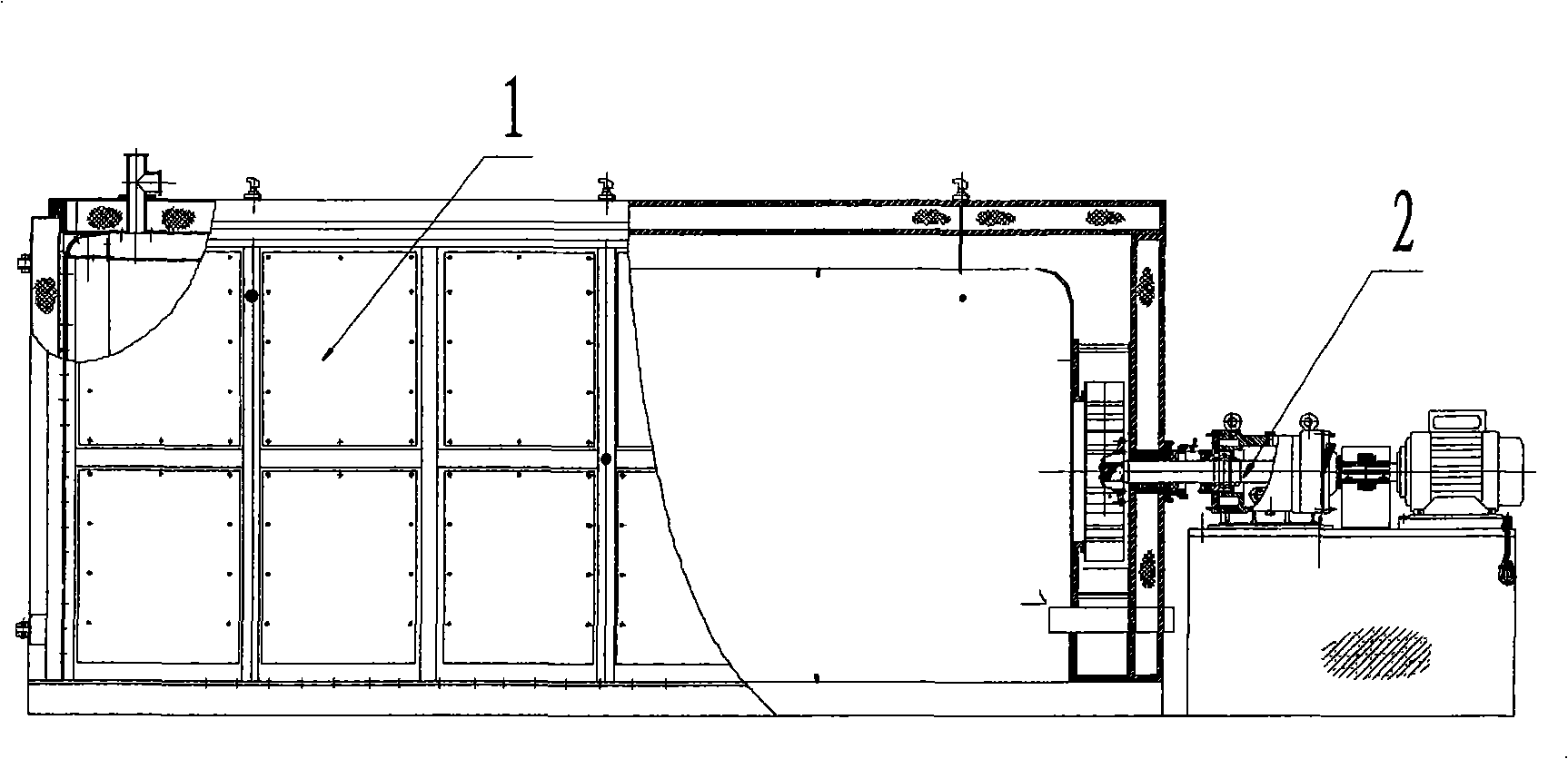
[0022] Such as figure 1 As shown, the overall structure of the present invention includes a furnace body 1 and a power unit 2 . The furnace body 1 is a cuboid structure.

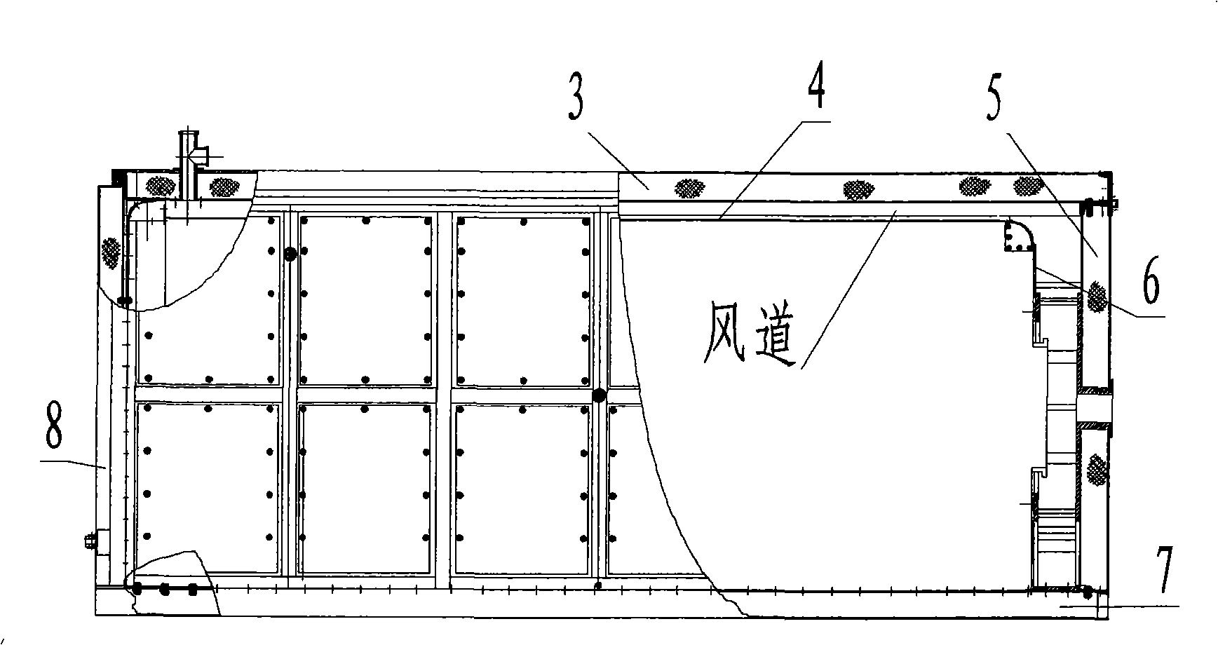
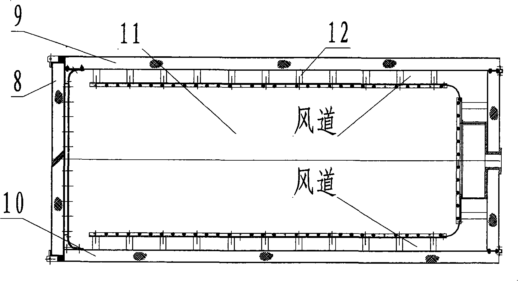
[0023] Such as figure 2 and image 3 As shown, the composition of the furnace body 1 includes: two side walls 9 and 10 of the furnace body, a top wall 3, a deflector 4, a rear wall 5, a rear deflector 6, a furnace door 8, a base 11, and the like. The side walls 9 and 10, the top wall 3, the rear wall 5, and the base 8 are all frame structures, and the connection between the outer plate and the frame adopts welding and screw connection, the inner plate is fixed with the frame by welding, and the connection between the furnace walls is threaded connection. On the inner sidewalls 9 and 10 of the body of furnace, a fixed connection frame is welded on the top wall 3, and t...


PUM


Abstract

The invention relates to an aeroheating furnace and a method for generating heat energy. The aeroheating furnace realizes heating by adopting the principle of converting wind energy into heat energy aThe invention relates to an aeroheating furnace and a method for generating heat energy. The aeroheating furnace realizes heating by adopting the principle of converting wind energy into heat energy al cavity channels of the furnace body and a furnace cavity to realize the conversion from wind energy to heat energy. The aeroheating furnace is essentially different from industrial furnaces generaall cavity channels of the furnace body and a furnace cavity to realize the conversion from wind energy to heat energy. The aeroheating furnace is essentially different from industrial furnaces generating heat by means of fuel combustion or directly converting electric energy into heat in principle. Moreover, the aeroheating furnace carries out heating and heat air circulation at the same time toting heat by means of fuel combustion or directly converting electric energy into heat in principle. Moreover, the aeroheating furnace carries out heating and heat air circulation at the same time torealize even height of temperature field inside the furnace body; in addition, the furnace does not adopt heating elements such as electrothermal tubes and reduces energy consumption to realize the efrealize even height of temperature field inside the furnace body; in addition, the furnace does not adopt heating elements such as electrothermal tubes and reduces energy consumption to realize the effect of energy saving.fect of energy saving.nd is characterized by comprising a furnace body and a power device, wherein the inside of the furnace body is provided with flow deflector arranged parallelly to the top wall, side walls and the backnd is characterized by comprising a furnace body and a power device, wherein the inside of the furnace body is provided with flow deflector arranged parallelly to the top wall, side walls and the backwall of the furnace body; wall cavity channels communicated upwards, leftwards, rightwards and backwards are formed in gaps between the flow deflector and the furnace walls, and are communicated with wall of the furnace body; wall cavity channels communicated upwards, leftwards, rightwards and backwards are formed in gaps between the flow deflector and the furnace walls, and are communicated with the intracavity of the furnace body at the front part of the furnace body; the power device comprises an electric motor, a transmission shaft and an impeller; the transmission shaft is fixed by a coothe intracavity of the furnace body at the front part of the furnace body; the power device comprises an electric motor, a transmission shaft and an impeller; the transmission shaft is fixed by a cooling support seat; and the electric motor is controlled by a control system to drive the impeller to rotate through the transmission shaft, thereby ensuring that high-speed air circulates inside the wling support seat; and the electric motor is controlled by a control system to drive the impeller to rotate through the transmission shaft, thereby ensuring that high-speed air circulates inside the wal

Description

technical field [0001] The invention relates to a heating furnace and a method for generating heat energy, in particular to an aerodynamic heating furnace and a method for generating heat energy, which are used for solid rocket motor production and solidification and for the carbonization of rocket motor shells, and can also be used for drying objects , Carbonization or vulcanization heating industrial furnace. Background technique [0002] With the development of my country's economy, the demand for energy is increasing, and my country has become a big energy consumer. In terms of electricity, our country has been in short supply for several years, and some areas even have "electricity shortages". In order to solve this problem, on the one hand, it is necessary to increase power facilities to increase power generation; on the other hand, it is necessary to reduce power consumption. However, the electric heating furnaces currently used by most enterprises in our country ha...

Claims


Application Information

Patent Timeline
Patent Type & Authority Patents(China)
IPC IPC(8): F24J3/06F24V50/00
Inventor 王照波张永侠李文岛张宏迅寇朝辉胡润芝野延年王艳辉肖琳赵永明
Owner XIAN AEROSPACE CHEM PROPULTION PLANT
Why Eureka
Try Eureka