Electric equipment shielding effectiveness test system and method

A technology of shielding effectiveness and electronic equipment, applied in the direction of measuring electricity, measuring devices, measuring electrical variables, etc., can solve problems such as damage to sensitive equipment, instability, etc., to ensure versatility, reduce manual intervention, improve test efficiency and test repetition sexual effect

Inactive Publication Date: 2014-03-12
陕西海泰电子有限责任公司
View PDF6 Cites 34 Cited by
  • Summary
  • Abstract
  • Description
  • Claims
  • Application Information

AI Technical Summary

Problems solved by technology

[0005] In order to solve the technical problems of damage to sensitive equipment and instability in existing shielding effectiveness testing methods, the present invention pro...

Method used


Image

  • Electric equipment shielding effectiveness test system and method
  • Electric equipment shielding effectiveness test system and method

Examples


Embodiment Construction

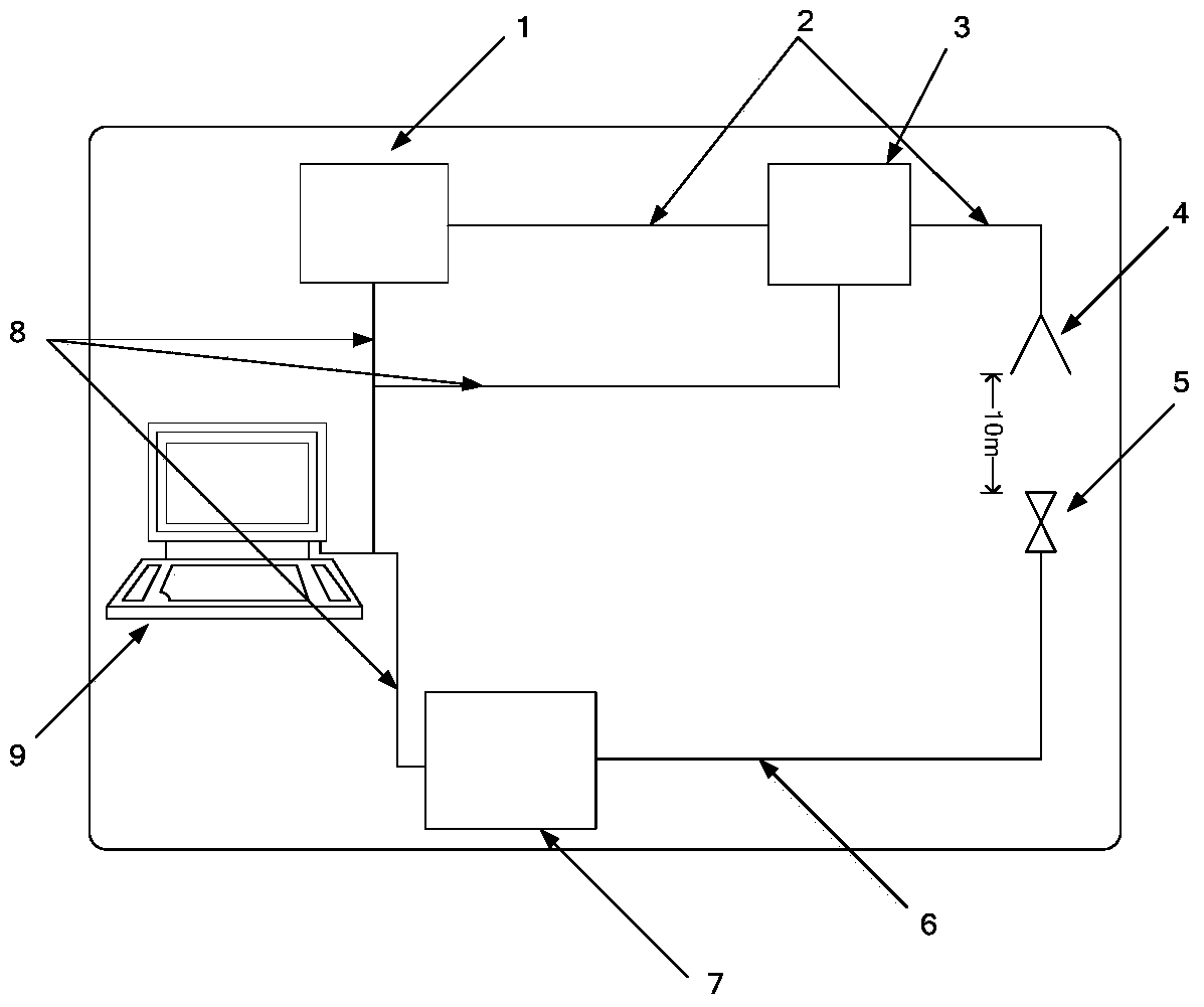
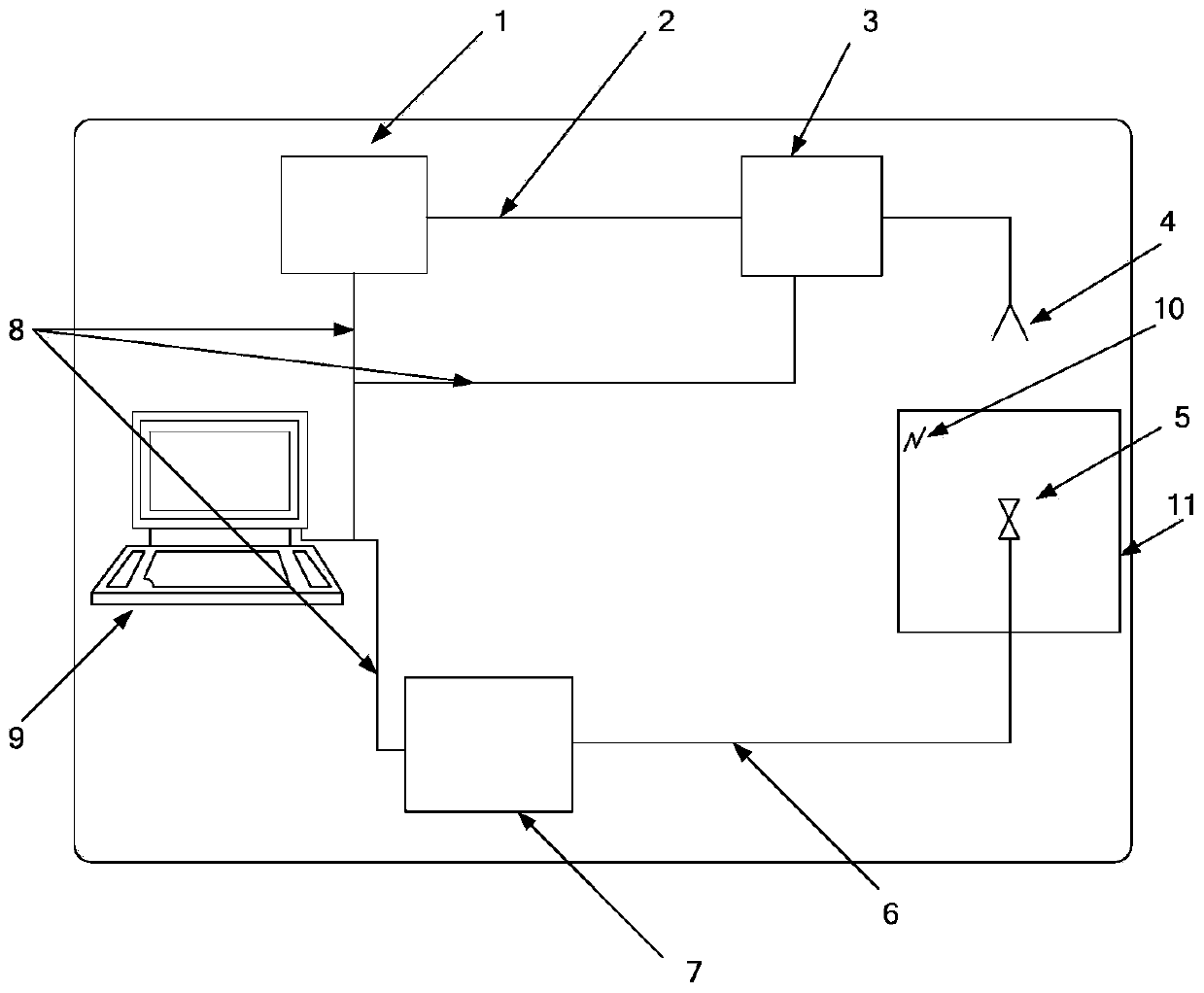
[0049] The electronic equipment shielding effectiveness test system includes two main parts: field strength calibration and internal field measurement. combine figure 1 and figure 2 , to describe the specific embodiments of the present invention in detail, but the embodiments of the present invention are not limited thereto.

[0050] 1. Field strength calibration configuration and principle

[0051] The test configuration for field strength calibration is as follows figure 1shown. The main purpose of field strength calibration is to measure the low-level calibration electric field generated by the transmitting antenna at a distance of 10m, as a basis for comparing the electric field in the shielded cabin.

[0052] During calibration, the distance between the transmitting antenna and the receiving antenna is 10m, the height of the transmitting antenna is adjustable, and the measuring system is calibrated by receiving signals from the receiving antenna. During calibration,...


PUM


Abstract

The invention relates to an electric equipment shielding effectiveness test system and method. The electric equipment shielding effectiveness test system comprises a radio frequency signal source, a power amplifier, an emission antenna, a receiving antenna, a spectrum analyzer or receiver and a control computer; one end of the radio frequency signal source is connected with one end of the power amplifier; the other end of the power amplifier is connected with the emission antenna mounted on a height-adjustable emission antenna support; during calibration, the receiving antenna is mounted on a receiving antenna support; during measurement, the receiving antenna is fixed in a shielding chamber of an object to be tested; the spectrum analyzer or the receiver is used for receiving the radio frequency signal measured by the receiving antenna; the output end of the spectrum analyzer or the receiver is connected with the control computer. The electric equipment shielding effectiveness test system and method effectively solve the technical problems of damage to sensitive equipment and instability of the existing shielding effectiveness test method, and can be applied to the radiation sensitivity test of the electric equipment under an HIRF (high intensity radiated field) environment.

Description

technical field [0001] The invention relates to the technical field of electromagnetic compatibility testing, and refers to a system for testing the shielding effectiveness of electronic equipment. Background technique [0002] With the wide application of electronic displays, control systems and composite materials, the electromagnetic susceptibility of electronic systems such as aircraft and ships is getting higher and higher. On the other hand, the electromagnetic environment problems caused by human activities are becoming more and more serious. Due to the radiation of high-power transmitters such as radar, radio, television, and satellite uplink data, high-intensity radiation fields (High Intensity Radiation Fields, HIRF) have become an important factor affecting the safety of electronic systems such as aircraft and ships. In order to ensure the safe operation of electronic systems under HIRF, radiation sensitivity tests under HIRF are required for electronic systems. ...

Claims


Application Information

Patent Timeline
IPC IPC(8): G01R31/00
Inventor 郭恩全陈晨杜浩赵乾
Owner 陕西海泰电子有限责任公司
Why Eureka
Try Eureka