
A distributed waveform generation online synchronization adjustment circuit and method

A waveform generation circuit and synchronous adjustment technology, used in radio wave measurement systems, instruments, etc., can solve problems such as difficult to precise control, output signal difference, signal frequency difference, etc., to achieve the effect of flexible waveform types and high synchronization accuracy

Inactive Publication Date: 2015-11-18
WUHAN BINHU ELECTRONICS
View PDF5 Cites 0 Cited by
  • Summary
  • Abstract
  • Description
  • Claims
  • Application Information

AI Technical Summary

Problems solved by technology

However, the radar using distributed waveforms has the following disadvantages: the difference in the channel output signal caused by the difference in the characteristics of the analog channel between the channels; the difference in the output signal caused by the batch difference of the device; It is difficult to precisely control the process, but the consistency of the waveform output in the distributed radar transceiver components will directly affect the energy synthesis of the radar in space, and then affect the key indicators of the radar such as the power coverage of the radar, so this problem Whether it can be effectively solved has become one of the main bottlenecks in improving the performance of such system radars
In the design process of distributed waveform generation radar, since the signal generation part is relatively independent in physical space, it is difficult for this method to solve the problem of synchronization differences between channels and batches of distributed signal generation
[0004] In phased array radar, the synchronization problem of transceiver components in the form of distributed signal generation mainly includes phase synchronization and time synchronization. Phase synchronization can be phase-shifted and corrected by the radar's own correction network to correct the phase difference of signals between channels. , but when there is a delay difference between the output signals when the signal is generated, it will cause a frequency difference between the signals between the channels at the same time
The most commonly used signals in the actual work of radar are linear frequency modulation signal and nonlinear frequency modulation signal. This patent takes linear frequency modulation signal as an example. According to the signal characteristics, the phase difference between channels will increase with time. In this case, the The resulting phase difference cannot be corrected by the correction network, which eventually leads to distortion of the result of radar space energy synthesis, which seriously affects the overall performance of the radar

Method used


Image

  • A distributed waveform generation online synchronization adjustment circuit and method
  • A distributed waveform generation online synchronization adjustment circuit and method

Examples


Embodiment Construction

[0022] The present invention will be further described below in conjunction with the accompanying drawings.

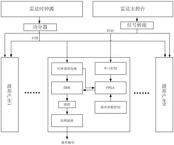
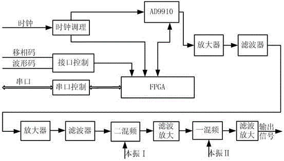
[0023] An online synchronization design method based on distributed radar waveform generation, such as figure 2 Shown is a block diagram of the structure of the system, the system is mainly composed of clock conditioning unit, DDS chip AD9910, serial port interface chip MAX232E and FPGAEP2C70F672I8, in which the clock conditioning unit is connected with the DDS chip and FPAG, the serial port interface chip is connected with FPGA, and the DDS chip AD9910 The output end of the radar FM waveform generated by the chip is connected with the input end of the frequency conversion, filtering and amplifying circuit, and its output port is directly connected with the output port. The beneficial effect is: generating radar frequency modulation waveform signals with low stray, low phase noise, high resolution and high synchronous precision between channels.

[0024] Through the ...


PUM


Abstract

The invention belongs to the technical field of synchronous comprehensive design for radar distributed waveform generation, and particularly relates to an online synchronous regulating circuit and method for use in distributed waveform generation. A main control terminal completes controlled communication with a waveform generation part in a receiving-transmitting assembly, and setting and adjustment of relevant parameters such as the leading edge and lagging edge of waveform output and initial frequency are realized according to a preset communication protocol. The online synchronous regulating circuit has the advantages of low cost, convenience and rapidness in operation, high accuracy, simple structure and easiness in integration.

Description

technical field [0001] The invention belongs to the technical field of synchronous comprehensive design of radar distributed waveform generation, and in particular relates to an online synchronization adjustment circuit and method for distributed waveform generation. Background technique [0002] Phased array radar waveform generation design can be mainly divided into centralized waveform generation and distributed waveform generation design. The centralized waveform generation design is to isolate the intermediate frequency signal generated by the unified waveform and provide it to each transceiver component. This method The disadvantage is that each transmission signal has a uniform form and cannot be changed flexibly; distributed waveform generation means that each transceiver component has an independent waveform generation unit. Compared with centralized waveform generation, it has obvious advantages such as flexible waveform control and high phase shifting accuracy. Ho...

Claims


Application Information

Patent Timeline
Patent Type & Authority Patents(China)
IPC IPC(8): G01S7/28
CPCG01S7/282
Inventor 苑凤雨李建垚徐晓罗华
Owner WUHAN BINHU ELECTRONICS
Learn More