Grid driving circuit and grid driving method

A gate drive circuit and drive signal technology, applied in the direction of instruments, static indicators, etc., can solve the problems of increasing the circuit area of ​​the shift register, reducing the visible area of ​​the display panel, increasing the production cost, etc. The effect of reducing size, simplifying complexity

Active Publication Date: 2014-03-12
AU OPTRONICS CORP
View PDF4 Cites 4 Cited by
  • Summary
  • Abstract
  • Description
  • Claims
  • Application Information

AI Technical Summary

Problems solved by technology

In order to allow each pixel to write the signal voltage in a short period of time, the shift register circuit must provide a higher driving voltage to drive the pixel transistor, but this will increase the area of ​​the shift register circuit and increase the production cost.
In addition, since the shift register circuit is directly fabricated on the frame of the display panel, the increase in the area of ​​the shift register circuit will also increase the frame of the display panel, resulting in a decrease in the visible area of ​​the display panel.

Method used


Image

  • Grid driving circuit and grid driving method
  • Grid driving circuit and grid driving method
  • Grid driving circuit and grid driving method

Examples


Embodiment Construction

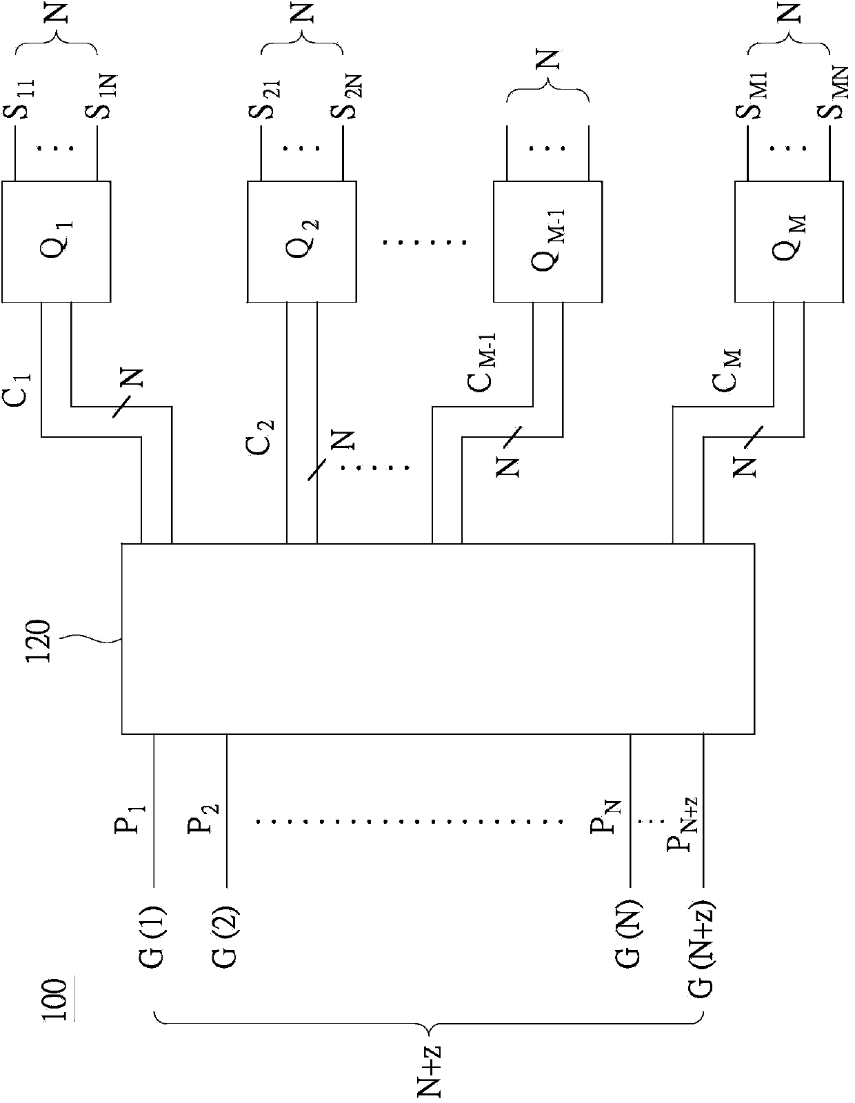
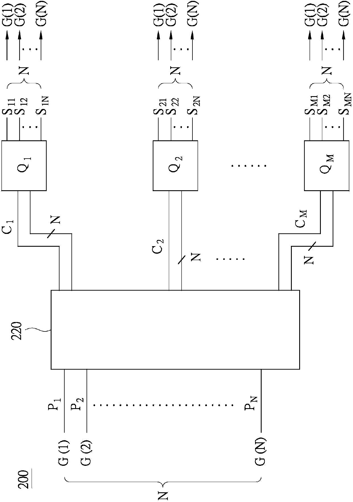
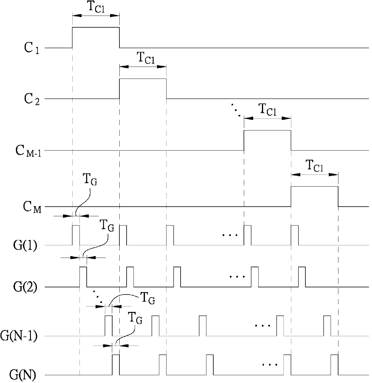
[0030] Please refer to figure 1 , figure 1 It is a schematic diagram of a gate driving circuit 100 according to an embodiment of the present invention. Such as figure 1 As shown, the gate drive circuit 100 includes at least N signal lines P 1 ,P 2 ,...,P N ,...,P N+z , M switch modules Q 1 , Q 2 ,...,Q M-1 , Q M , and the control module 120, wherein N represents the number of scan lines connected to each switch module, and z is an integer greater than or equal to zero. N+z signal lines P 1 ~P N+z It is used to transmit driving signals corresponding to the number of signal lines, that is, N+z driving signals G(1), G(2), . . . , G(N), . . . , G(N+z). Each driving signal is a periodic continuous timing signal, and the duty cycle (duty cycle) of each driving signal is 1 / (N+z).

[0031] Each switch module is electrically connected to N scanning lines S M1 ~S MN (M is the corresponding switch module). Therefore, the gate drive circuit 100 has M*N scanning lines S in ...


PUM


Abstract

The present invention provides a grid driving circuit and a grid driving method. The grid driving circuit of the invention comprises at least N signal lines, M switch modules and a control module. At least N signal lines are used for transmitting at least N driving signals. Each switch module is coupled with N scanning lines. The control module is coupled between at least N signal lines and N scanning lines of each switch module for generating M control signals for respectively controlling corresponding M switch modules, wherein when one in the M control signals causes a corresponding switch module conducted, the control module selects the driving signal of N successive signal lines in the N signal lines and successively transmits to N scanning lines of the conducted switch modules. The control module successively causes the M switch modules to be conducted for transmitting successive M*N driving signals.

Description

technical field [0001] The invention relates to a gate drive circuit, in particular to a gate drive circuit with a plurality of switch modules. Background technique [0002] In an active matrix liquid crystal display (Active Matrix Liquid Crystal Display), each pixel contains a thin-film transistor (Thin-Film Transistor, TFT), the gate of which is connected to the horizontal scanning line, and the source is connected to the vertical direction. data line, while the drain is connected to the pixel electrode. If a certain scanning line in the horizontal direction provides enough positive voltage, all the transistors on the scanning line will be turned on, and the pixel electrode on the scanning line will be connected to the data line in the vertical direction, and the signal of the data line will be The voltage is written into each pixel capacitor of the scan line to control the light transmittance of different pixel liquid crystals to achieve the effect of color control. [...

Claims


Application Information

Patent Timeline
Patent Type & Authority Applications(China)
IPC IPC(8): G09G3/36
Inventor 洪凯尉詹秉燏陈勇志张晴惠
Owner AU OPTRONICS CORP
Why Eureka
Try Eureka