Passive waste heat discharge system of nuclear power station steam generator secondary side

A steam generator and passive waste heat technology, applied in steam generation, nuclear power generation, steam boilers, etc., can solve problems such as failure, unit loss of ability to discharge waste heat from the core, and inability to guarantee the safety of nuclear power plants

Inactive Publication Date: 2014-03-12
NUCLEAR POWER INSTITUTE OF CHINA
View PDF2 Cites 13 Cited by
  • Summary
  • Abstract
  • Description
  • Claims
  • Application Information

AI Technical Summary

Problems solved by technology

This kind of accident response measures relying on active equipment may fail under complex accident environment conditions
Once the steam-driven pump water supply series of the auxiliary water supply system fails, the unit will lose the ability to discharge the waste heat from the core, and the safety of the nuclear power plant (station) cannot be guaranteed.

Method used


Image

  • Passive waste heat discharge system of nuclear power station steam generator secondary side
  • Passive waste heat discharge system of nuclear power station steam generator secondary side
  • Passive waste heat discharge system of nuclear power station steam generator secondary side

Examples


Embodiment 1

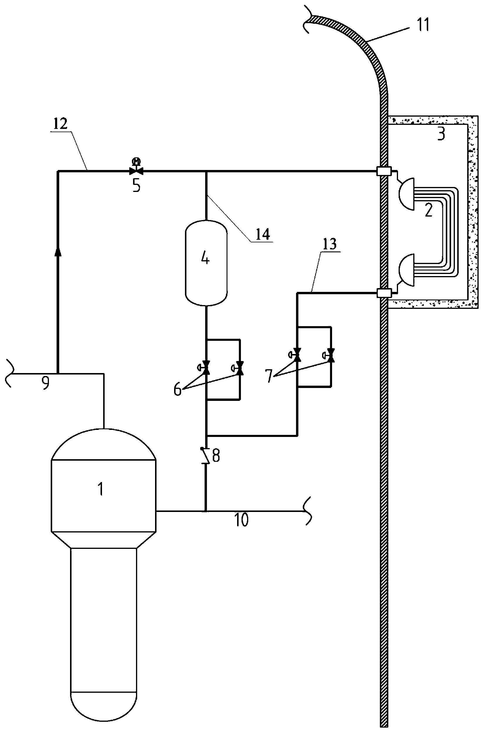
[0022] Such as figure 1 The present invention shows a passive waste heat removal system on the secondary side of a steam generator in a nuclear power plant. The waste heat removal system includes a cooling water tank 3 arranged on the periphery of a reactor containment 11 and filled with water. The containment 11 of the reactor has a cylinder The cylinder body, the cooling water tank 3 has a ring-shaped structure and is arranged at a higher position outside the containment vessel 11. The civil structure and the containment vessel are uniformly designed. The cooling water tank 3 is provided with a water replenishment structure and a drainage structure for The cooling water tank 3 drains water during replenishment and maintenance.

[0023] The heat exchanger 2 is submerged in the bottom of the cooling water tank 3, and water inlets and outlets are arranged on the upper and lower heads of the heat exchanger.

[0024] One end of the first waste heat discharge pipeline 12 passes t...

Embodiment 2

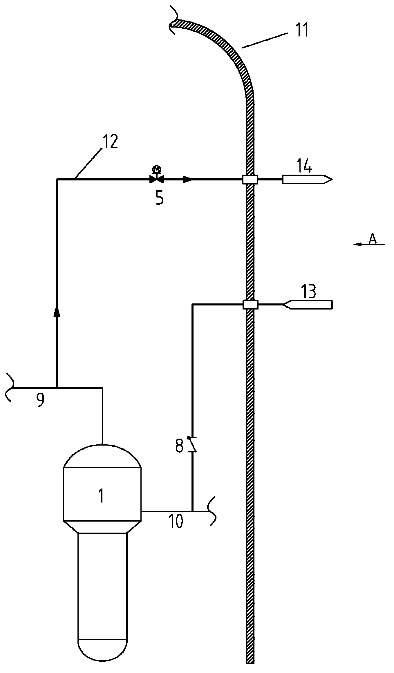
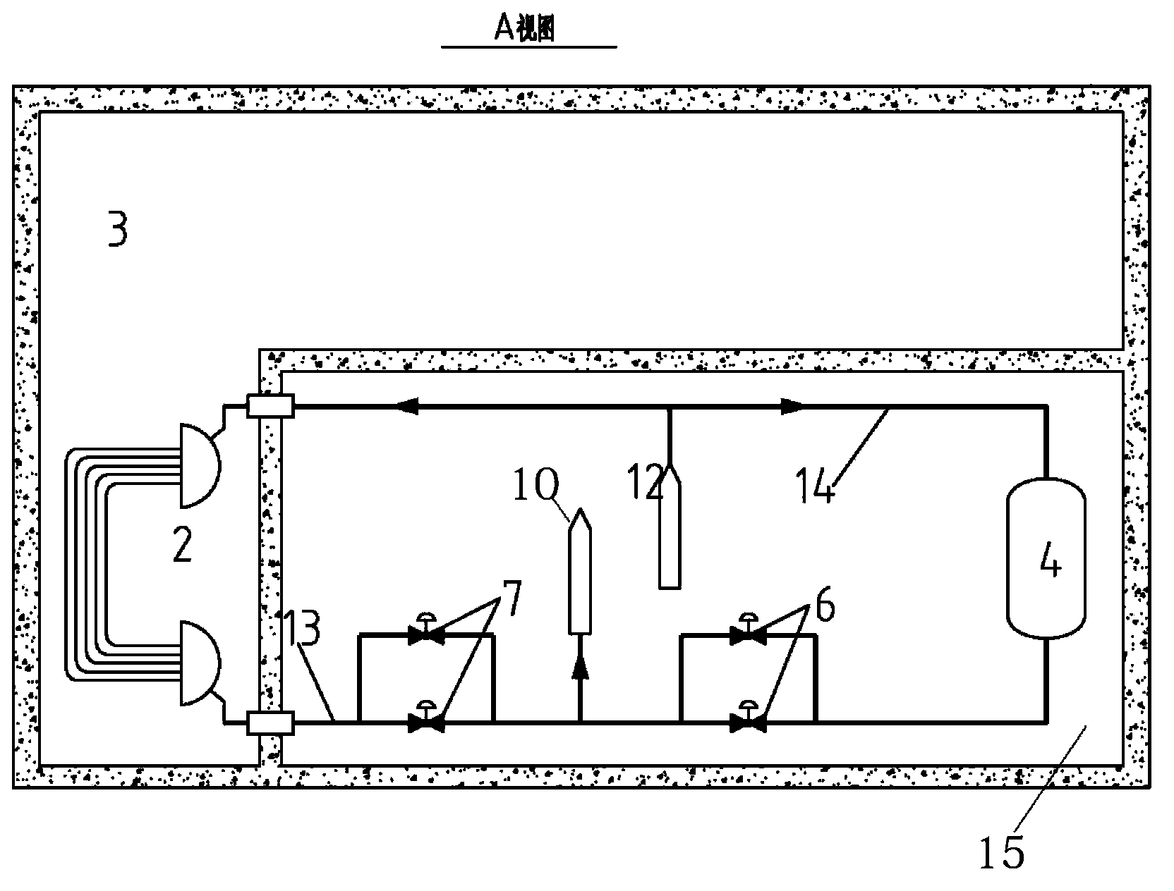
[0029] Such as figure 2 , image 3 As shown, the difference from Embodiment 1 is that the first isolation valve group 6 , the second isolation valve group 7 and the make-up water tank 4 are all arranged in the concrete equipment compartment 15 outside the containment.

Embodiment 3

[0031] The difference from Embodiment 1 is that the first isolation valve group 6 and the second isolation valve group 7 are located inside the containment, and the water supplement tank 4 is arranged in the concrete equipment compartment 15 outside the containment.


PUM


Abstract

The invention relates to a passive waste heat discharge system of a nuclear power station steam generator secondary side. The passive waste heat discharge system comprises a cooling water tank which is arranged on the outer part of a containment vessel of a reactor and is filled with water, a heat exchanger which is immersed at the bottom of the cooling water tank, a first waste heat discharge pipe of which one end goes through the containment vessel and then is connected to an inlet of the heat exchanger, a steam pipe isolating valve which is arranged on the first waste heat discharge pipe, a second waste heat discharge pipe of which one end goes through the containment vessel and then is connected to an outlet of the heat exchanger, and a first isolating valve set which is arranged on the second waste heat discharge pipe; the other end of the first waste heat discharge pipe is connected to a steam pipe on an upper end of a steam generator; and the other end of the second waste heat discharge pipe is connected to a water feeding pipe of the steam generator. The passive waste heat discharge system can discharge reactor core waste heat for a long time and keep a reactor safe state in a passive way by a steam/water density difference as a driving force under the conditions of station blackout and complete loss of a dynamic reactor core waste heat discharge capacity of the electric field.

Description

technical field [0001] The invention relates to a nuclear power plant waste heat discharge system, in particular to a nuclear power plant steam generator secondary side passive waste heat discharge system. Background technique [0002] After a nuclear power plant (station) power outage accident occurred, the main pump was shut down, the reactor coolant flow rate dropped sharply, and the feed water on the secondary side of the steam generator was lost at the same time, resulting in a decrease in the heat transfer capacity of the steam generator and the heat generated by the core. Buildup in the reactor coolant system, causing the system temperature to rise. After a plant-wide blackout accident, whether the remaining heat release can be effectively discharged for a long time is related to the safety of the nuclear power plant (station). [0003] In the past, nuclear power plants could only provide feed water to the secondary side of the steam generator through the steam-drive...

Claims


Application Information

Patent Timeline
Patent Type & Authority Applications(China)
IPC IPC(8): G21C15/18
CPCG21D3/06Y02E30/40G21C15/12G21C13/02G21C15/18F22B37/002Y02E30/00Y02E30/30
Inventor 黄伟任云赖建永张玉龙隋海明
Owner NUCLEAR POWER INSTITUTE OF CHINA
Why Eureka
Try Eureka