Antenna structure integrated in metal shell

A metal shell and antenna structure technology, applied in the direction of antenna equipment with additional functions, radiating element structure, etc.

Inactive Publication Date: 2014-03-12
HONG FU JIN PRECISION IND (SHENZHEN) CO LTD +1
View PDF2 Cites 17 Cited by
  • Summary
  • Abstract
  • Description
  • Claims
  • Application Information

AI Technical Summary

Problems solved by technology

[0006] Using the above-mentioned invention, the antenna structure integrated in the metal casing has a slit on the side of the metal casing, one end of the side is in contact with the antenna radiation circuit, and the other end is grounded, so that the slit of the casing can be used as the antenna radiation circuit. Part of it is to solve the problem that the traditional antenna must avoid the metal shell, so that the antenna has better characteristics and meets the requirements of product miniaturization

Method used


Image

  • Antenna structure integrated in metal shell
  • Antenna structure integrated in metal shell
  • Antenna structure integrated in metal shell

Examples


Embodiment Construction

[0015] The present invention will be further described in detail below in conjunction with the accompanying drawings.

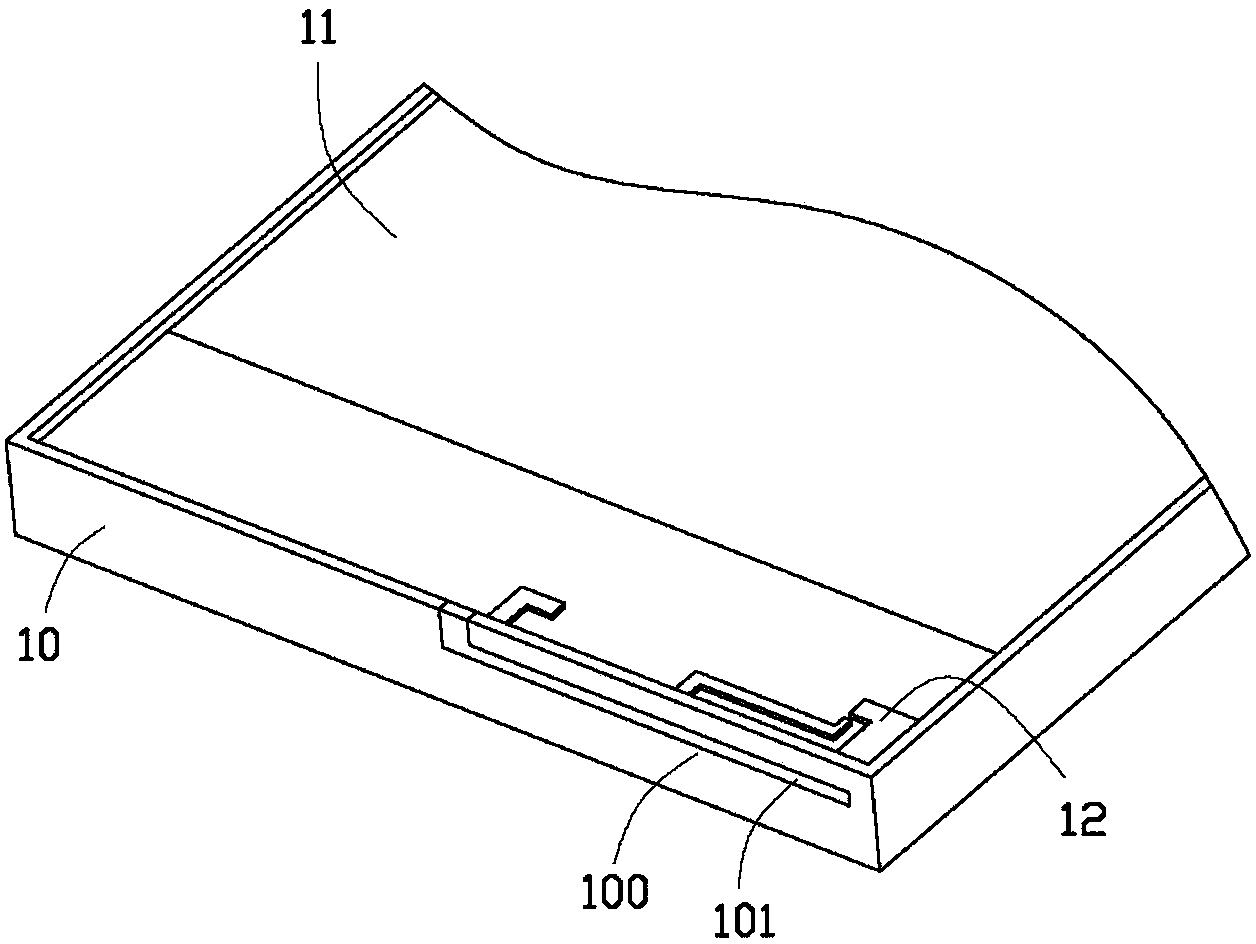
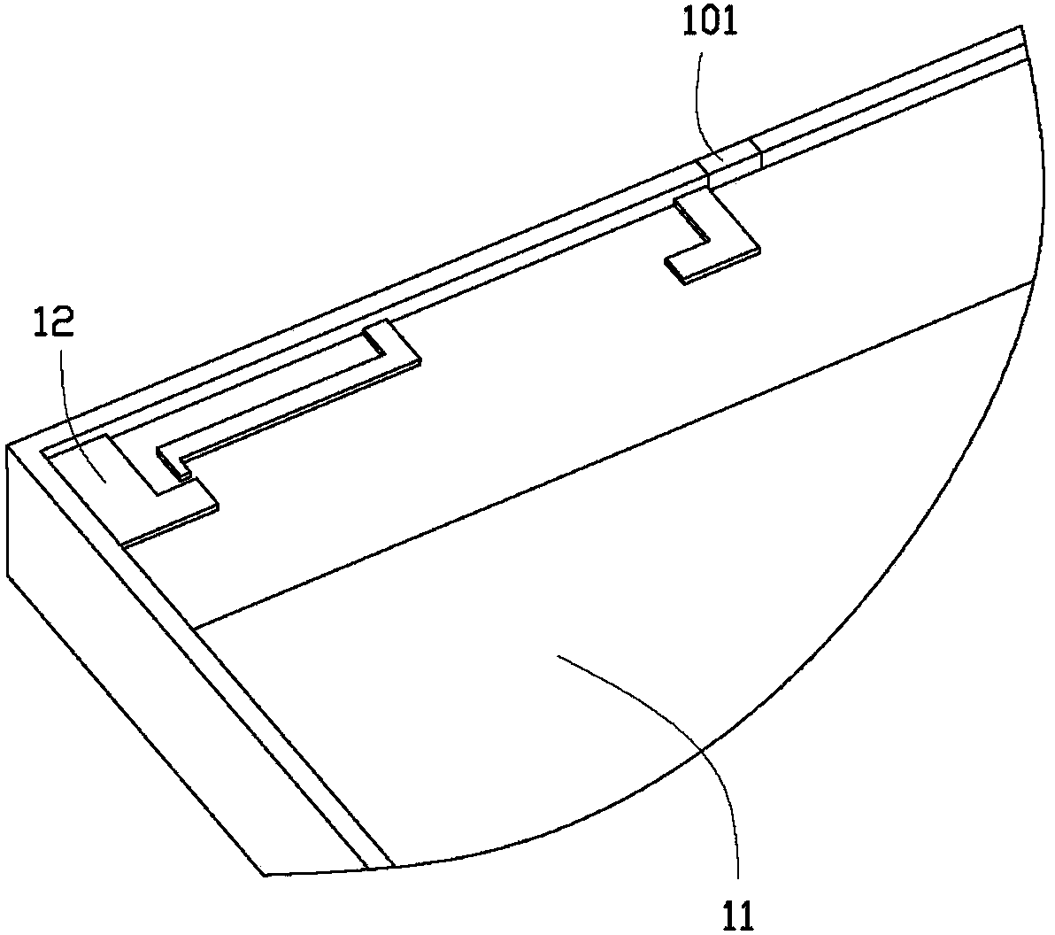
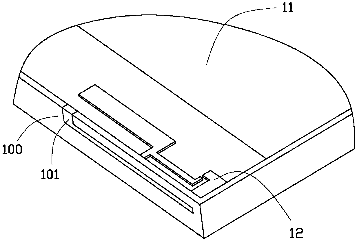
[0016] Please also see figure 1 and 2 , is a partial schematic diagram of the antenna structure integrated in the metal housing in the first embodiment of the present invention. The antenna structure integrated in the metal casing has a casing 10 of an electronic device, a circuit substrate 11 disposed in the casing 10 and an antenna radiation line 12 disposed on the circuit substrate 11 .

[0017] Wherein, the housing 10 includes a plurality of sides 100 , one of the sides 100 defines a slit 101 passing through the side 100 . The shell 10 is a metal shell made of metal material, and the side 100 with the slit 101 is processed to form a complete metal surface. In this embodiment, the slit 101 is L-shaped, and the longer side of the L-shape is opened along the edge of the long side of the side 100 , and the shorter side is opened in a direction perpendicula...


PUM


Abstract

The invention provides an antenna structure integrated in a metal shell. The antenna structure comprises a metal shell of an electronic device, a circuit substrate arranged in the metal shell, and an antenna radiation circuit, wherein the antenna radiation circuit with a certain shape is formed by bending of a long bar-shaped metal and is arranged at the circuit substrate. The metal shell includes a plurality of side surfaces; and a slit is arranged at one of the multiple side surfaces. One end of the antenna radiation circuit is contacted with the side surface provided with the slit and approaches one end of the slit; and the side surface that is not contacted with the antenna radiation circuit and approaches the other end of the slit is grounded. With the antenna structure, because the slit is arranged at one side of the metal shell, and one end of the side is contacted with the antenna radiation circuit and the other end is grounded, the slit of the shell is used as one part of the antenna radiation circuit, so that a problem that the existing antenna has to avoid to use a shell made of the metal material can be solved; and thus the antenna has the good characteristics and the product miniaturization requirement is also met.

Description

technical field [0001] The invention relates to an antenna structure integrated in a metal casing. Background technique [0002] Due to the development of wireless communication technology, electronic products are paying more and more attention to the quality of signal reception, such as the global positioning system (GPS) navigation function or mobile communication capabilities. At the same time, the electronics industry requires electronic products to be light, thin, short, and small, plus highly integrated chip features to achieve the purpose of miniaturization. [0003] At present, the electronic products on the market will cover the circuit board and the antenna structure with a metal casing. The metal casing has the advantages of high strength, not easy to damage, and a metal texture. This results in poor efficiency of the antenna structure. Therefore, in order to solve the problem of incompatibility between the characteristics of the metal case and the antenna, it i...

Claims


Application Information

Patent Timeline
Patent Type & Authority Applications(China)
IPC IPC(8): H01Q1/44H01Q1/36
Inventor 林彦辉刘建昌
Owner HONG FU JIN PRECISION IND (SHENZHEN) CO LTD
Why Eureka
Try Eureka