Self-detection method for positions of rotors of switched reluctance motors

A technology of switched reluctance motor and rotor position, which is applied in the direction of electronic commutator, etc., can solve the problems of low detection accuracy and real-time performance, and achieve the effects of good model generalization ability, easy implementation, and simple rules

Inactive Publication Date: 2014-03-12
JIANGSU UNIV
View PDF4 Cites 13 Cited by
  • Summary
  • Abstract
  • Description
  • Claims
  • Application Information

AI Technical Summary

Problems solved by technology

[0004] The purpose of the present invention is to solve the problem that the existing switched reluctance motor rotor position detection method has low detection accuracy and real-time pe...

Method used


Image

  • Self-detection method for positions of rotors of switched reluctance motors
  • Self-detection method for positions of rotors of switched reluctance motors
  • Self-detection method for positions of rotors of switched reluctance motors

Examples


Embodiment Construction

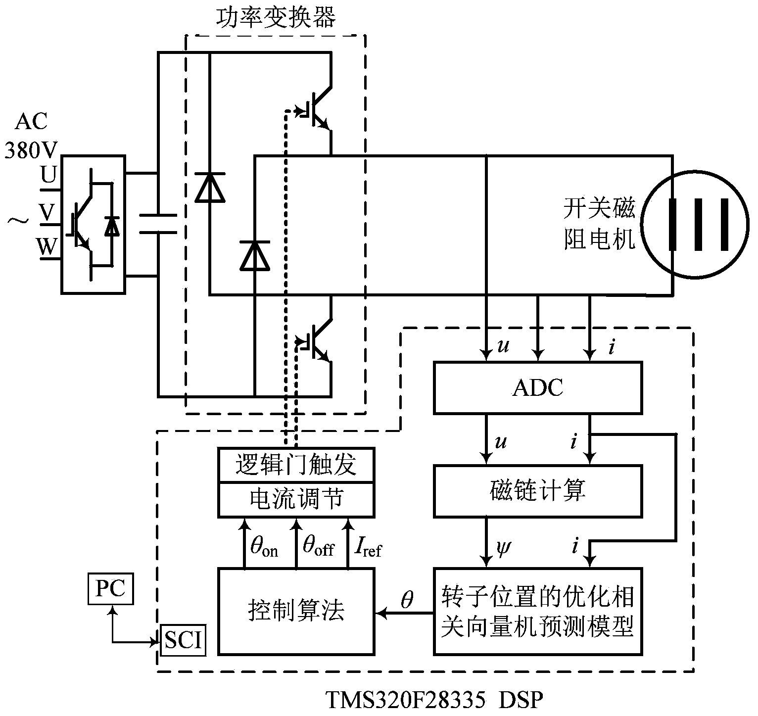
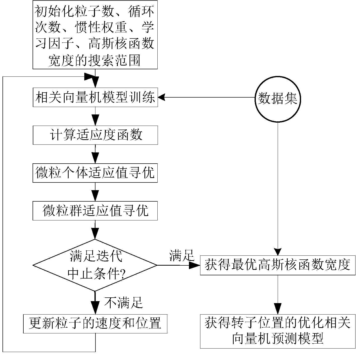
[0013] The implementation of the present invention is divided into three parts. The first part is to obtain learning samples through the sampling of the switched reluctance motor experimental system. The second part is the establishment of the particle swarm optimization correlation vector machine off-line prediction model of the rotor position of the motor. The third part is to pass the detection The phase current and phase voltage predict the rotor position angle of the motor in real time, as follows:

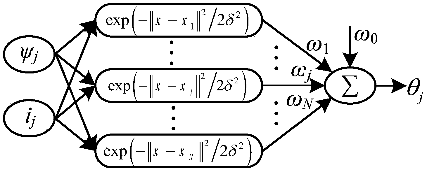
[0014] Step 1: Perform closed-loop sampling through the switched reluctance motor experimental system to obtain training and testing samples. Sampling phase current i, voltage u, rotor position θ, and according to ψ j (k)=ψ j (k-1)+0.5T[u j (k)-ri j (k)+u j (k-1)-ri j (k-1)] to obtain the flux linkage ψ j ; among them, ψ j (k), ψ j (k-1) are the flux linkage calculation values ​​at the kth sampling moment and the k-1th sampling moment respectively, u j (k), u j (k-1...


PUM


Abstract

The invention discloses a self-detection method for positions of rotors of switched reluctance motors. The self-detection method includes building prediction models of relevant vector machines and acquiring parameters of particle swarm optimization models; estimating position angles of the rotors by the aid of the nonlinear prediction models for the positions of the rotors; performing self-detection on the positions of the rotors of the motors. By the aid of the self-detection method, shortcomings of long decision-making time, poor instantaneity and the like due to complicated models in the traditional intelligent detection method can be overcome, and the self-detection method has the advantages of good generalization ability, short online computation time, high prediction precision and the like, and is applicable to performing quick self-detection on the positions of the rotors of the switched reluctance motors in full-speed running ranges.

Description

technical field [0001] The invention belongs to the technical field intersecting special electric power transmission and information science, in particular to a method for self-detecting the rotor position of a switched reluctance motor. Background technique [0002] Due to its high efficiency, low cost, simple structure, reliable operation, and wide speed range, switched reluctance motors have been widely used in traction transportation, aviation industry, mining and textiles and other fields. Switched reluctance motors adopt position closed-loop control, and generally measure the rotor position signal directly by installing a position sensor, but the mechanical sensor not only increases the cost and complexity of the system, but also affects the reliability of the entire motor drive system, especially in high-speed operation. stage. [0003] At present, for the switched reluctance motor, many literatures have proposed the detection method of the rotor position, such as th...

Claims


Application Information

Patent Timeline
IPC IPC(8): H02P6/18
Inventor 项倩雯吉敬华嵇小辅康梅
Owner JIANGSU UNIV
Why Eureka
Try Eureka