Cooling system

A cooling system, cooling cycle technology, used in liquid cooling, engine cooling, machine/engine, etc., to solve problems such as aggravation

Inactive Publication Date: 2014-03-12
ZF FRIEDRICHSHAFEN AG
View PDF5 Cites 11 Cited by
  • Summary
  • Abstract
  • Description
  • Claims
  • Application Information

AI Technical Summary

Problems solved by technology

This exacerbates the problems described a

Method used


Image

  • Cooling system
  • Cooling system

Examples


Embodiment Construction

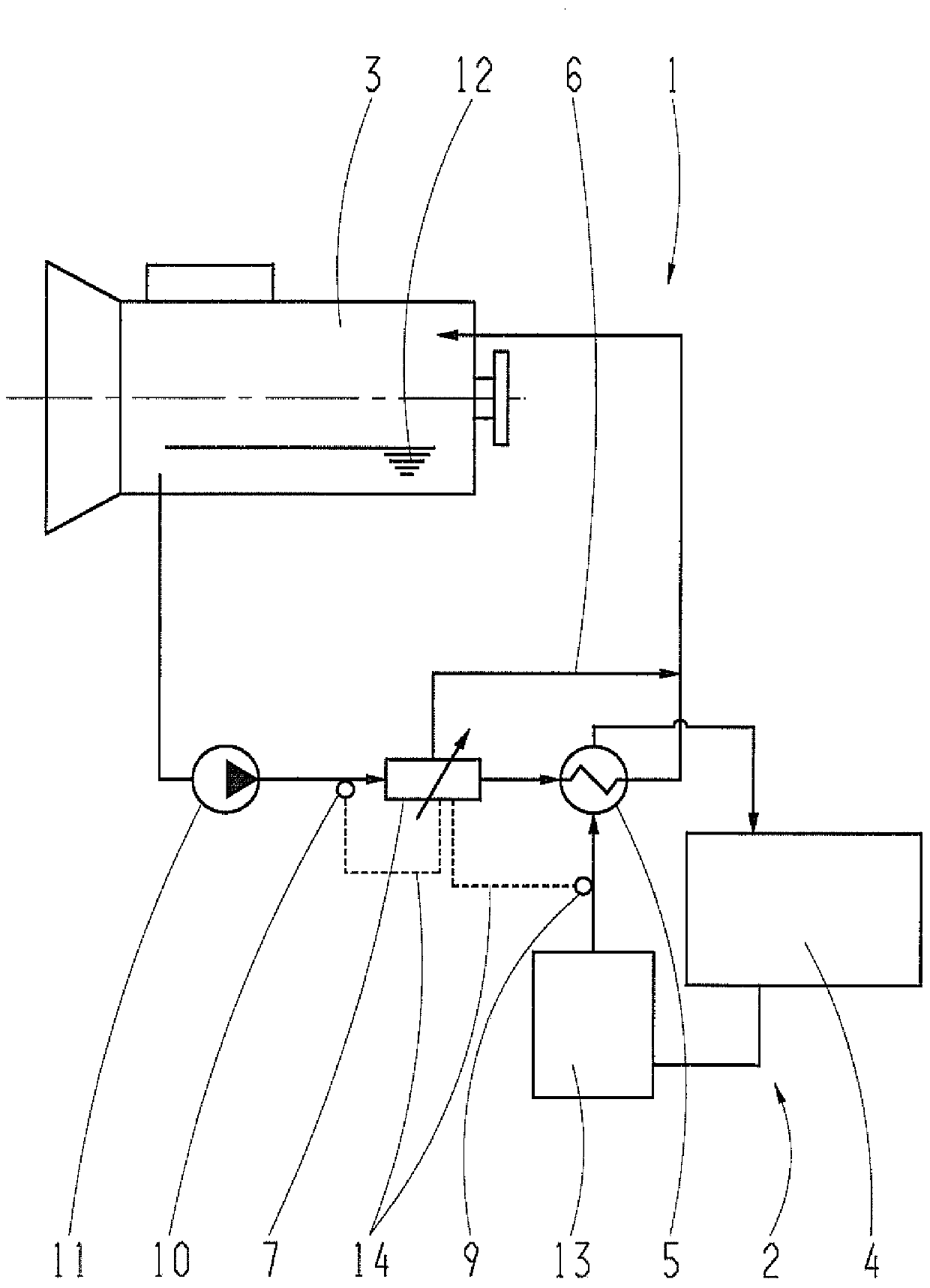
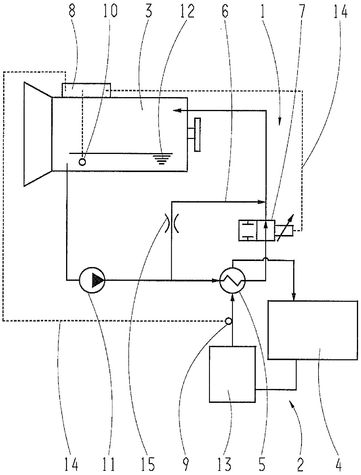
[0023] The transmission oil pump 11 draws transmission oil from an oil sump 12 of the transmission 3 and delivers it through the transmission cooling circuit 1 . The transmission cooling circuit 1 includes a heat exchanger 5 , with the aid of which heat energy generated in the transmission 3 can be transferred to the cooling water circuit 2 of the internal combustion engine 4 . Thermal energy from the transmission 3 and the internal combustion engine 4 is discharged from the cooling water circuit 2 to the surrounding air through the vehicle cooler 13 .

[0024] in accordance with figure 1 In the transmission cooling circuit 1 , a control element 7 in the form of a thermostat is arranged between the transmission oil pump 11 and the heat exchanger 5 . One of the two output lines of the thermostat 7 is connected to the input side of the heat exchanger 5 and the other is connected to the output side of the heat exchanger 5, so that the transmission oil flow is guided through the ...


PUM


Abstract

The invention relates to a cooling system for a vehicle having a transmission cooling circuit (1) which discharges the thermal energy generated in the transmission (3) via a heat exchanger (5) to a cooling water circuit (2) of an internal combustion engine (4). In the process, the transmission cooling circuit (1) comprises a bypass line (6) for bypassing the heat exchanger (5), and a control element (7). The bypass line (6) can be activated by the control element (7) with the result that the heat exchanger (5) can be bypassed in the transmission cooling circuit (1). The control element (7) can be actuated as a function of a temperature in the cooling water circuit (2).

Description

technical field [0001] The invention relates to a cooling system for a vehicle according to the preamble of claim 1 and a vehicle according to claim 8 with such a cooling system. Background technique [0002] Various systems are known for cooling the transmission of a vehicle, which include a transmission cooling circuit which discharges heat energy generated in the transmission via a heat exchanger to the cooling water circuit of the internal combustion engine. The cooling water circuit of the internal combustion engine usually dissipates the heat energy to be dissipated into the surrounding air via a water-air cooler. During certain operating phases, the temperature in the cooling water circuit of the internal combustion engine rises so strongly that thermal energy can no longer be discharged from the transmission cooling circuit via the heat exchanger, but instead is fed into the transmission in the opposite direction In the cooling circuit, this leads to an undesired in...

Claims


Application Information

Patent Timeline
IPC IPC(8): F01P3/20F01M5/00
CPCF01P3/20F16H57/0413F01P2060/045
Inventor 卡尔-弗里茨·海因策尔曼
Owner ZF FRIEDRICHSHAFEN AG
Why Eureka
Try Eureka