Method for heating a battery module

A technology for battery packs and power consumers, which is applied in the field of battery pack modules and can solve problems such as low energy density

Pending Publication Date: 2019-12-03
ROBERT BOSCH GMBH
View PDF2 Cites 1 Cited by
  • Summary
  • Abstract
  • Description
  • Claims
  • Application Information

AI Technical Summary

Problems solved by technology

"Electric double layer capacitors" and "pseudocapacitors" have

Method used


Image

  • Method for heating a battery module
  • Method for heating a battery module
  • Method for heating a battery module

Examples


Embodiment Construction

[0038] In the subsequent description of embodiments of the invention, identical or similar elements are identified with the same reference numerals, a repeated description of these elements being omitted in individual cases. These figures represent the subject matter of the invention only schematically.

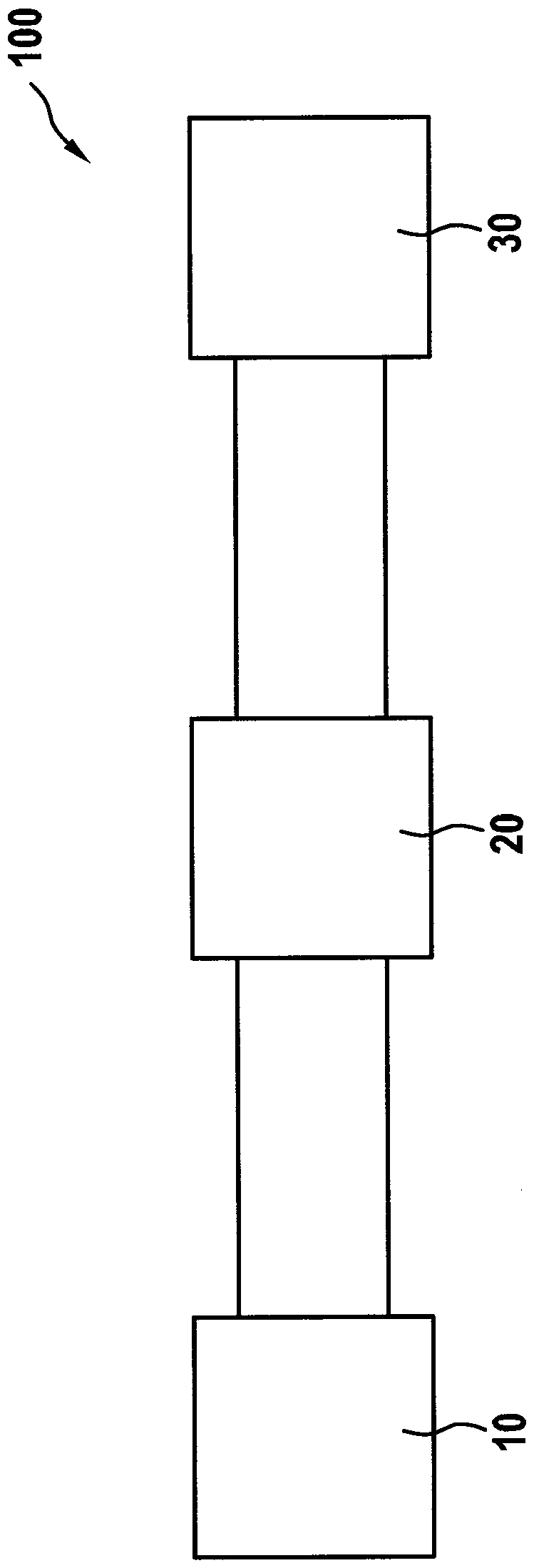
[0039] figure 1 A schematic diagram of a first specific embodiment of a device 100 for carrying out the method according to the invention is shown. The device 100 includes in particular a battery module 30 which can be, for example, a starter battery of a motor vehicle with an internal combustion engine, a traction battery of a motor vehicle with an electric drive or a backup battery of a backup system of a motor vehicle.

[0040] The device 100 also includes an electrical energy store 10 , which differs from the battery module 30 , and which is designed as a supercapacitor or as a hybrid supercapacitor.

[0041] The device 100 also includes an inverter 20 , which is fed by...


PUM


Abstract

The invention relates to a method for heating a battery module (30) of a motor vehicle. The battery module (30) is heated by means of a high-frequency alternating current generated by an inverter (20), the inverter (20) being fed by an electrical energy store (10) that is different from the battery module (30) and is designed as a supercapacitor or a hybrid supercapacitor , The inverter (20) is athree-phase inverter, the three phases of the output of which are connected to a three-phase consumer, two phases of the output being connected to the battery module (30) for heating. The invention further relates to an arrangement (100, 200) and a motor vehicle, which are set up to carry out a method for heating a battery module (30).

Description

technical field [0001] The invention relates to a method for heating a battery module of a motor vehicle. The battery module is heated by means of a high-frequency alternating current generated by an inverter, which is also called an inverter and comprises an input and an output, wherein the inverter is formed differently from the battery module The electric energy accumulator is fed by an electric energy accumulator, which is configured as a supercapacitor or a hybrid supercapacitor. The invention also relates to a device and a motor vehicle which are designed to carry out a method for heating a battery module. Background technique [0002] With the increasing electrification of motor vehicles, especially passenger vehicles (PKW), more and more systems are being built which require electrical energy stores, such as starter batteries, traction batteries or backups Backup battery pack for the system. Most of these electrical energy stores must be charged and available when...

Claims


Application Information

Patent Timeline
IPC IPC(8): H01M10/42H01M10/615H01M10/625H01M10/657H02J7/34B60L58/27
CPCB60L58/27H01M10/4264H01M10/615H01M10/625H01M10/657H01M2220/20H02J7/345B60L1/02B60L58/20B60L2210/40H01M10/443H02J7/1446Y02E60/10Y02T10/70Y02T10/72Y02T10/92
Inventor L.博默M.多诺特克
Owner ROBERT BOSCH GMBH
Why Eureka
Try Eureka