Machine for automatic assembly and detection of automotive connector and implementation method of machine

An automotive connector and automatic assembly technology, applied in assembly machines, metal processing equipment, manufacturing tools, etc., can solve the problems of wasting human resources, inaccurate assembly accuracy, and low production efficiency, reducing labor intensity and improving production efficiency. , the effect of saving labor costs

Active Publication Date: 2014-03-19
CHENGDU TIANCHUANG PRECISION MOLD
6 Cites 18 Cited by

AI-Extracted Technical Summary

Problems solved by technology

This production method is not only prone to missing, under-installed, and reverse-installed parts, and inaccurate assem...

Abstract

The invention discloses a machine for automatic assembly and detection of an automotive connector. The machine comprises a cabinet, a forming part, a protective cover and a controller, wherein an electric control component is arranged inside the cabinet, the forming part is connected with the cabinet and used for product assembly and formation, the protective cover is installed on the cabinet and used for protecting the forming part, and the controller is used for controlling the forming part to act; the forming part comprises a bottom plate, a rotating station as well as a sealing block feeding detection station, a plastic casing assembly detection station, a seal ring assembly detection station, a large plastic casing assembly detection station, a rear cover assembly detection station and a discharge marking station which are installed on the bottom plate and evenly distributed clockwise along the outer circumference of the rotating station, the bottom plate is connected with the cabinet, and the rotating station is arranged on the bottom plate and used for rotating and circulating assembly of products. According to the machine, a plurality of assembly stations are integrated in one automatic assembly machine in a rotary table high-speed rotation manner, so that the floor space of equipment is greatly reduced, the machine is more practical and more automatic, the labor cost is saved, and the pass percent of the products is increased.

Application Domain

Technology Topic

EngineeringAssembly machine +1

Image

  • Machine for automatic assembly and detection of automotive connector and implementation method of machine
  • Machine for automatic assembly and detection of automotive connector and implementation method of machine
  • Machine for automatic assembly and detection of automotive connector and implementation method of machine

Examples

  • Experimental program(1)

Example Embodiment

[0049] Example
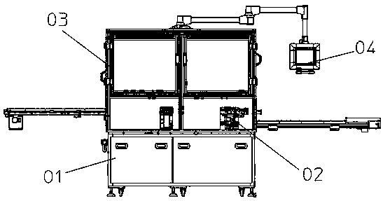
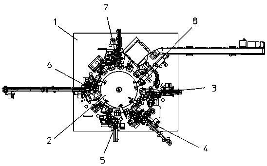
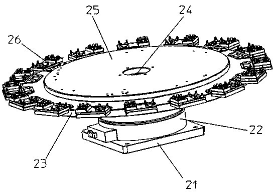
[0050] Such as Figure 1 to Figure 13 As shown, the machine for automatic assembly and testing of automobile connectors includes a cabinet 01 with built-in electrical control components, a molding part 02 connected to the cabinet for product assembly and molding, and installed on the cabinet to protect the protection of the molding part. The cover 03 and the controller 04 for controlling the action of the forming part; wherein, the controller can be realized by an existing general PLC control method, which will not be repeated in this embodiment. The forming part includes a bottom plate 1 connected to the cabinet, a rotating station 2 arranged on the bottom plate for product rotation and assembly, and sealing blocks that are installed on the bottom plate and evenly distributed along the clockwise rotation of the outer circumference of the rotating station. Loading inspection station 3, small plastic housing assembly inspection station 4, sealing ring assembly inspection station 5, large plastic housing assembly inspection station 6, rear cover assembly inspection station 7 and discharge marking station 8. Among them, the specific structure of each station is as follows:
[0051] Such as image 3 As shown, the rotating station includes a base 21 installed on the bottom plate, a CKD16 index plate 22 arranged on the base for index rotation, and a fixed support connected to the base through the center of the CKD16 index plate 24. The rotating disc 23, which is driven by the CKD16 index plate, is sleeved on the fixed support, the fixed disc 25 connected to the fixed support, and 16 are all installed on the CKD16 index plate and are connected with the sealing block. Supporting mechanism for mounting products and accessories respectively corresponding to the position, small plastic shell assembly and testing station, sealing ring assembly and testing station, large plastic shell assembly and testing station, rear cover assembly and testing station, and discharge marking station. 26.
[0052] Such as Figure 4 As shown, the fixing plate 261 of the supporting mechanism is installed on the rotating disc, the mounting plate 262 is arranged on the fixing plate, and the clamping block 263 is arranged on the left side of the fixing plate for fixing the large plastic shell. The positioning block 264 is installed on the mounting plate. The right side of the board is provided with positioning pins 265 and positioning pins 266, which are used to fix the sealing ring and the small plastic shell.
[0053] Such as Figure 5 As shown, the sealing block feeding detection station includes a sealing block feeding belt line mechanism 31 for feeding materials located outside the rotating station, which is connected to the sealing block feeding belt line mechanism to facilitate a single installation of a sealing block dislocation mechanism 32. The sealing block installation reverse detection mechanism corresponding to the end of the sealing block feeding belt line mechanism and used to detect the positive and negative of the sealing block incoming material 33, which is connected with the sealing block dislocation mechanism and used to transport the sealing block incoming material to the rotating station The seal block conveying mechanism 34 and the seal block rotating mechanism 35 connected to the seal block conveying mechanism for turning the incoming seal block in the reverse state to the right. The seal block support seat 311 of the seal block feeding belt line mechanism is fixed on the bottom plate. The seal block support seat is provided with a seal block belt line motor assembly 312 and a seal block displacement mechanism. The seal block flow channel 313 is fixed on the seal block belt. The line motor assembly is equipped with a sealing block belt 314, which effectively connects the two in relation to each other. The sealing block flow path is also provided with a sealing block pressing bearing 315 and a sealing block stop block 316. The sealing block The end of the flow channel is also equipped with a sealing block incoming fiber optic sensor 317; the sealing block dislocation mechanism includes a sealing block dislocation support seat 321 connected to the sealing block support seat, which is arranged on the sealing block dislocation support seat and enters the sealing block. The sealing block displacement flow passage 322 connected to the material belt line mechanism, the sealing block displacement cylinder 323 connected to the sealing block displacement flow passage and controlling its reciprocating movement, the sealing block displacement limit buffer 324 arranged on the sealing block displacement flow passage, and The seal block displacement limit block 325 is installed on the seal block misalignment support seat; the seal block inversion detection support seat 331 of the seal block inversion detection mechanism is installed on the bottom plate, and the seal block inversion detection CCD332 is installed in the seal block installation On the counter support base; the transport support base 341 of the seal block transport mechanism is installed on the bottom plate, the servo motor transport module 342 is installed on the transport support base and can be displaced by 180 degrees, and the servo motor transport module is also connected with a seal block Transport T-block 343, seal block transport T-block is provided with a seal block transport installation plate 344, seal block transport installation plate is equipped with a seal block transport cylinder 345 and linear bearing 346, and the linear bearing is equipped with a seal block transport Shaft 347, one end of the seal block conveying shaft is fixedly connected to the seal block conveying head 348 and a spring is arranged between the two, and the seal block conveying cylinder is connected to the seal block conveying head to drive the seal block conveying head to move up and down; the seal The rotating support seat 351 of the block rotating mechanism is installed on the bottom plate. The center circular hole of the horizontal plate A352 of the rotating support seat is provided with a bushing 353. The rotating shaft 354 is equipped with a bearing and placed in the bushing. The upper end of the rotating shaft is installed Seal block bearing 355, the lower end part is connected with motor 357 through coupling 356, and the motor is fixed on the horizontal plate B358 of the rotating support seat, the optical fiber sensor A359 is also arranged above the seal block bearing and installed on the transport support seat .
[0054] Such as Image 6 As shown, the small plastic shell assembly and inspection station includes a small plastic shell feeding belt line mechanism 41 for feeding materials located outside the rotating station, which is connected with the small plastic shell feeding belt line mechanism to facilitate individual loading of small plastic The shell dislocation mechanism 42 is connected to the small plastic shell dislocation mechanism and used to transport the small plastic shell incoming materials to the rotating station and assemble the small plastic shell assembly and transfer mechanism 43, and the small plastic shell assembly and transfer mechanism connected to the small plastic shell assembly and transfer mechanism 43 Rotating mechanism 44. The small plastic shell support seat 411 of the small plastic shell feeding belt line mechanism is fixed on the bottom plate, and the small plastic shell support seat is provided with a small plastic shell belt line motor assembly 412 and a small plastic shell displacement mechanism, and a small plastic shell runner 413 is fixed on the small plastic shell belt line motor assembly, and a small plastic shell belt 414 is set in the two. The small plastic shell belt effectively connects the two. The front end of the small plastic shell runner is equipped with a small plastic shell full of material. The optical fiber sensor 415 is also provided with a small plastic shell at the end of the fiber sensor 416; the small plastic shell dislocation mechanism includes a small plastic shell dislocation support seat 421 connected to the small plastic shell support seat, and is arranged on the small plastic shell dislocation support seat A small plastic shell dislocation flow channel 422 connected to the small plastic shell feeding belt line mechanism, and a small plastic shell dislocation cylinder 423 connected to the small plastic shell dislocation flow channel and controlling its reciprocating movement is arranged on the small plastic shell dislocation flow channel The small plastic shell offset limit buffer 424, and the small plastic shell offset limit block 425 installed on the small plastic shell offset support seat, and the small plastic shell offset limit block 426; the small plastic shell handling mechanism The transport support base and the servo motor transport module have the same structure as the seal block transport mechanism. The servo motor transport module is also connected with a small plastic shell assembly block 431, and the small plastic shell assembly block is provided with a small plastic shell clamping jaw cylinder 432 , The small plastic shell clamping jaw cylinder is equipped with a chuck 433, and a small plastic shell pressing bracket 434 is also provided on the servo motor handling module. A small plastic shell pressing cylinder 435 is installed on the small plastic shell pressing bracket. Small plastic shell The compacting cylinder is provided with a small plastic shell compacting block 436; the structure of the small plastic shell rotating mechanism and the sealing block rotating mechanism are basically the same, the only difference is the small plastic shell bearing 441, here is not the small plastic shell rotating mechanism The structure is explained.
[0055] Such as Figure 7 As shown, the sealing ring assembly and detection station includes a sealing ring feeding belt line mechanism 51 for feeding materials located outside the rotating station, and a sealing ring feeding belt line mechanism connected to the sealing ring feeding belt line mechanism for conveying incoming seal ring materials to the rotating The seal ring assembly and transport mechanism 52 of the station corresponds to the position of the seal ring assembly and transport mechanism and is used to detect whether the seal ring is missing or not, and the seal ring assembly and transport mechanism cooperates with the seal ring to complete the seal ring assembly. Seal ring press in place mechanism 54. The sealing ring belt line motor assembly 511 of the sealing ring feeding belt line mechanism is fixed on the bottom plate, the sealing ring flow channel 512 is fixed on the sealing ring belt line motor assembly, and a sealing ring belt 513 is provided in the two sealing rings. The belt effectively connects the relationship between the two. The seal ring stop cylinder 514 is arranged on the seal ring flow channel. The end of the seal ring flow channel is also provided with a seal ring stop block 515 and a seal ring anti-deformation needle; the seal ring transport mechanism The structure of the conveying support base and the servo motor conveying module is the same as the sealing block conveying mechanism. The servo motor conveying module is also connected to the sealing ring assembly plate 521, the sealing ring slider 522 is fixed on the sealing ring assembly plate, and the sealing ring is sliding A sealing ring cylinder fixing plate 523 is also installed on the block. The sealing ring assembly cylinder 524 is fixed on the sealing ring cylinder fixing plate and is connected to the sealing ring sliding groove 525. The sealing ring sliding groove is slidingly connected to the sealing ring slider, and the sealing ring sliding The groove is also provided with a sealing ring assembly head 526; the sealing ring detection mechanism includes a sealing ring fiber mounting frame 531 and a sealing ring fiber optic sensor 532. The sealing ring fiber mounting frame is fixed on the fixed disc, and the sealing ring fiber optic sensor is fixed on the sealing ring. Ring optical fiber mounting frame; the sealing ring pressing support seat 541 of the sealing ring pressing mechanism is fixed on the bottom plate, the sealing ring pressing support seat is provided with a sealing ring pressing mounting plate 542, and the sealing ring pressing mounting plate The sealing ring pressing linear guide 543, the sealing ring pressing cylinder 544 and the sealing ring limit buffer 545 are respectively provided. The sealing ring pressing moving plate 546 is installed on the sealing ring pressing linear guide and connected with the sealing ring pressing cylinder. The sealing ring pressing moving plate is also provided with a sealing ring limiting block 547 and a sealing ring pressing head 548, and the sealing ring pressing in place optical fiber sensor 549 is installed on the sealing ring pressing support seat.
[0056] Such as Figure 8 with Picture 9 As shown, the large plastic housing assembly detection station includes a large plastic housing pre-assembly detection mechanism 61 corresponding to the position of the rotating station, a large plastic housing feeding belt line mechanism 62 for feeding outside the rotating station, and a large plastic housing The plastic shell feeding belt line mechanism is connected to the large plastic shell conveying mechanism 63 used to transport the large plastic shell incoming material to the rotating station, and the large plastic shell conveying mechanism is connected to the large plastic shell conveying mechanism to transfer the large plastic shell incoming material to the previously installed A large plastic shell assembly mechanism 64 for preliminary assembly of a good semi-finished product, a large plastic shell assembly in place mechanism 65 connected with the large plastic shell assembly mechanism for complete assembly of the large plastic shell, and a detection corresponding to the position of the rotating station Whether the large plastic casing is missing or not is assembled in place to detect the mechanism 66. The CCD mounting frame 611 of the detection mechanism before assembly of the large plastic housing is fixed on the bottom plate. The CCD mounting frame is provided with a CCD612. The light source of the CCD is illuminated from top to bottom. The CCD mounting frame is also provided with a semi-finished product with or without an optical fiber sensor. 613; the large plastic shell belt line motor assembly 621 of the large plastic shell feeding belt line mechanism is fixed on the bottom plate, the large plastic shell runner 622 is fixed on the large plastic shell belt line motor assembly, and a large plastic shell is provided in the two Plastic shell belt 623, the large plastic shell belt effectively connects the relationship between the two, the front end of the large plastic shell flow channel is provided with a large plastic shell feeding fiber optic sensor 624, the middle is provided with a large plastic shell full fiber sensor 625, and the end is also set There is a large plastic shell incoming fiber optic sensor 626; the structure of the large plastic shell handling mechanism and the servo motor handling module are the same as the seal block handling mechanism, and the servo motor handling module is also connected to the large plastic shell handling installation Plate 631, the large plastic shell carrying jaw cylinder 632 is installed on the large plastic shell carrying and mounting plate, and the large plastic shell carrying jaw cylinder is provided with a large plastic shell carrying chuck 633; ​​the large plastic shell assembly mechanism includes The large plastic shell assembly bracket 641 on the bottom plate is set with the rodless cylinder 642 on the large plastic shell assembly bracket. The rodless cylinder is equipped with a large plastic shell assembly fixing plate 643, and the large plastic shell assembly fixing plate is equipped with a pneumatic sliding table. 644. The pneumatic sliding table is provided with a large plastic shell assembly jaw cylinder 645, and the large plastic shell assembly chuck 646 is installed on the large plastic shell assembly jaw cylinder; the large plastic shell pressing support of the large plastic shell assembly in place mechanism The seat 651 is fixed on the bottom plate, the large plastic shell pressing support seat is provided with a large plastic shell pressing mounting plate 652, and the large plastic shell pressing mounting plate is respectively provided with a large plastic shell pressing linear guide 653 and a large plastic shell pressing mounting plate. The material cylinder 654 and the large plastic housing limit buffer 655, the large plastic housing pressing moving plate 656 is installed on the large plastic housing pressing linear guide and connected with the large plastic housing pressing cylinder, and the large plastic housing pressing moving plate is also A large plastic shell limit block 657 and a sealing ring pressing head 658 are provided; the large plastic shell assembly in place detection mechanism includes a CCD mounting frame 611 installed on the cabinet, and the light source is irradiated from bottom to top and installed in the CCD. CCD612 on the shelf.
[0057] Such as Picture 10 As shown, the rear cover assembly detection station includes a rear cover feeding belt line mechanism 71 for feeding materials located outside the rotating station, and a rear cover feeding belt line mechanism connected to the rear cover feeding belt line mechanism for conveying the back cover incoming material to the rotating Station and assembled rear cover assembly and transport mechanism 72, rear cover rotation mechanism 73 connected with the rear cover assembly and transport mechanism, and corresponding to the position of the rotating station for detecting whether the rear cover is missing and pressing the back cover into place Rear cover detection mechanism 74. The back cover belt line motor assembly 711 of the back cover feeding belt line mechanism is installed on the bottom plate, the back cover runner 712 is fixed on the back cover belt line motor assembly, and the back cover belt 713 is provided in the two, and the back cover The belt effectively connects the relationship between the two, the back cover stop cylinder 714 is provided on the back cover runner, and the back cover incoming fiber sensor 715 is also provided at the end; the conveying support seat of the back cover assembly and conveying mechanism and the servo motor conveying mold The structure of the group is the same as the sealing block transport mechanism. The servo motor transport module is also connected with a rear cover assembly block 721. The rear cover assembly block is provided with a rear cover clamping jaw cylinder 722, and the rear cover clamping jaw cylinder is equipped with a rear cover chuck 723. The servo motor handling module is also provided with a rear cover mounting reverse fiber sensor 724; the rear cover rotating mechanism and the sealing block rotating mechanism are basically the same in structure, with the only difference being the rear cover bearing 731. The structure of the plastic housing rotating mechanism will be described. The rear cover detection support seat 741 of the rear cover detection mechanism is fixed on the bottom plate, the rear cover detection support seat is provided with a rear cover detection mounting plate 742, and the rear cover detection mounting plate is respectively provided with a rear cover detection linear guide 743 and a rear cover. The cover detection cylinder 744 and the rear cover detection limit buffer 745. The rear cover detection moving plate 746 is installed on the rear cover detection linear guide and connected with the rear cover detection cylinder. The rear cover detection moving plate is also provided with a rear cover detection limit Block 747 and a back cover detection head 748, the back cover detection head is also provided with a back cover assembled fiber optic sensor 749.
[0058] Such as Picture 11 with Picture 12 As shown, the discharging marking station includes a discharging handling mechanism 81 corresponding to the rotating station for removing the assembled product, and connected to the discharging handling mechanism for detecting missing parts The defective product discharge mechanism 82 that discharges the products separately, the good product marking placement mechanism 83 connected to the discharge conveying mechanism for marking qualified assembled products, and the good product marking mechanism 84 connected to the good product marking placement mechanism. And a good product discharge mechanism 85 connected to the good product marking mechanism. The discharging conveying support seat 811 of the discharging and conveying mechanism is fixed on the bottom plate, and the discharging servo conveying module 812 is arranged on the discharging conveying support seat. The discharging cylinder 813 and the discharging linear guide 814 are arranged in the discharging servo conveying On the module, the discharging gripper bracket 815 is installed on the discharging linear guide and connected with the discharging cylinder. The discharging gripper bracket is also equipped with a discharging gripper cylinder 816, and the discharging gripper cylinder is provided with discharging. Chuck 817; the defective product discharge mechanism includes a defective product discharge channel 821 and a defective product receiving box 822. The defective product discharge runner is installed on the bottom plate, and the defective product receiving box is placed in the cabinet; the good product marking The placement mechanism includes a good product placement support seat 831 fixed on the bottom plate, and a good product placement support seat 832 set on the good product placement support seat; the marking machine support frame 841 of the good product marking mechanism is installed on the cabinet, and the marking machine 842 It is installed on the support frame of the marking machine, and the upper part of the marking machine is provided with a protective cover 843; the good product discharge mechanism includes a sheet metal runner 851 installed on the bottom plate, and a good product discharge optical fiber sensor 852 is provided on the sheet metal runner. The discharging runner support seat 853 is arranged on another automatic machine. The discharging belt line runner 854 is provided on the discharging runner support seat, and one end of the discharging belt line runner is set under the sheet metal runner to be able to receive For products discharged from the sheet metal runner, the discharge belt line runner is also provided with a discharge full fiber optic sensor 855 and a discharge runner speed regulator 856, respectively.
[0059] Such as image 3 As shown, the present invention also provides an implementation method of the machine for automatic assembly and detection of automobile connectors, which includes the following steps:
[0060] (1) The parts of the automobile connector are in the order of sealing block, small plastic shell, sealing ring, large plastic shell, and rear cover, and are fed by their corresponding feeding belt line mechanism. The feeding method is automatic vibration plate Loading, the rotating station rotates clockwise according to the setting of the CKD16 indexing plate, and the parts of the automobile connector are placed by the supporting mechanism. There are 16 supporting mechanisms corresponding to each station. For the convenience of description, the following text The supporting mechanism is called a work station, that is, from one work station to sixteen work stations, the bearing used to fix the sealing ring and the small plastic shell on the supporting mechanism is called the bearing one, and the one used to fix the large plastic shell The socket is called socket two;
[0061] (2) Taking a certain supporting mechanism as the benchmark, when it is in a station, the sealing block feeding belt line mechanism will sequentially transport the sealing block to the sealing block dislocation mechanism. After the sealing block enters the sealing block dislocation flow channel, the sealing block The installation reverse detection mechanism detects the positive and negative of the incoming material of the sealing block. After the detection is completed, the sealing block dislocation cylinder controls the dislocation flow channel of the sealing block to move to the first position of the sealing block handling mechanism. At this time, the sealing block is in place and the optical fiber sensor detects When the seal block is reached, the signal is given, the seal block carrying head moves to the first position to transport the seal block to the seal block socket, the optical fiber sensor A detects that the seal block is placed on the socket, and the seal block reverse detection mechanism rotates to the seal block The mechanism gives a signal. If the incoming direction of the seal block is opposite to the required direction, the seal block rotating mechanism will rotate 180 degrees to the required direction, otherwise it will not rotate; then the seal block transport mechanism will transport the seal block in the correct direction to The bearing seat of the supporting mechanism of the rotating disc is on, and the rotating disc rotates to the next station;
[0062] (3) The second station is a reserved station, and no operations are performed on this station;
[0063] (4) When the supporting mechanism carrying the sealing block moves to the Sangong station, the small plastic shell feeding belt line mechanism will sequentially transport the small plastic shell to the small plastic shell dislocation mechanism, and wait for the small plastic shell to enter the small plastic shell dislocation flow channel Then, the small plastic shell is loaded with a fiber optic sensor to detect the positive and negative of the small plastic shell. After the detection, the small plastic shell dislocation cylinder controls the movement of the small plastic shell dislocation flow path to the first position of the small plastic shell handling mechanism At this time, the small plastic shell is in place and the optical fiber sensor detects the small plastic shell to give a signal. The small plastic shell chuck moves to the first position to move the small plastic shell to the small plastic shell socket, and the optical fiber sensor A detects the socket A small plastic shell is placed on the plastic shell. The anti-optical fiber sensor sends a signal to the small plastic shell rotating mechanism. If the incoming direction of the small plastic shell is opposite to the required direction, the small plastic shell rotating mechanism will perform 180 degrees. Rotate to the required direction, otherwise it will not rotate; then the small plastic shell assembly and transport mechanism assembles and transports the small plastic shell in the correct direction to the supporting mechanism of the rotating disc, and assembles the sealing block in the small plastic shell;
[0064] (5) As the rotating disc rotates to the Sigong station, at this time, the small plastic shell compression cylinder drives the small plastic shell compression block to move downwards, and the seal block is assembled in the small plastic shell, and then moves to the next station. station;
[0065] (6) At the Wugong station, the sealing ring feeding belt line mechanism sequentially transports the sealing ring to the first position of the sealing ring transportation, and the sealing ring assembly cylinder controls the sealing ring assembly head to clamp the sealing ring and transport it to the position of the bearing seat 1. , And then assemble the sealing ring to the small plastic shell;
[0066] (7) Then move to the Liugong station, the optical fiber sensor of the sealing ring will detect whether there is any missing installation, and move to the next station after the detection;
[0067] (8) At Qigong station, the sealing ring pressing cylinder controls the sealing ring pressing moving plate so that the sealing ring pressing head assembles the sealing ring in place on the small plastic shell, and at the same time the sealing ring is pressed in place. The optical fiber sensor detects the assembly position. , And then move to the next station;
[0068] (9) When the assembled semi-finished product is at the eight-work station, the CCD detects whether there are missing parts in the first seat, and whether the semi-finished product has an optical fiber sensor to detect whether there are any parts in the second seat. , The second seat has no parts, and then flows into the next station for operation;
[0069] (10) When in the Jiugong station, the large plastic shell feeding belt line mechanism sequentially transports the large plastic shell to the first position of the large plastic shell handling. At this time, the large plastic shell incoming fiber optic sensor detects the large plastic shell. The shell carrying jaw cylinder controls the large plastic shell carrying chuck to clamp the large plastic shell and transport it to the second seat;
[0070] (11) Shigong Station is a reserved station, and no operations are performed on this station;
[0071] (12) When moving to the eleventh station, the rodless cylinder drives the large plastic shell assembly head to move downwards. At this time, the large plastic shell assembly jaw cylinder controls the large plastic shell assembly head to transport the semi-finished products on the first seat to the bearing On the second seat, and assembled on the large plastic shell;
[0072] (13) Immediately after moving to the twelve station, the large plastic shell pressing cylinder controls the movement of the large plastic shell pressing moving plate, so that the large plastic shell pressing head will assemble the product in place, and the large plastic shell will be assembled in place by the CCD of the detection mechanism. Check whether the second assembly of the socket is in place and whether there is any missing installation;
[0073] (14) When entering the thirteenth station, the rear cover feeding belt line mechanism will sequentially transport the rear cover to the first position of the rear cover handling. At this time, the rear cover incoming optical fiber sensor detects the back cover and gives a signal. Move the head to the first position to transport the back cover to the back cover holder. The optical fiber sensor A detects that the back cover is placed on the holder and detects the incoming direction of the back cover. If the incoming direction of the back cover is opposite to the required direction, At this time, the rear cover rotating mechanism will rotate 180 degrees to the required direction, otherwise it will not rotate; then the rear cover assembly and transport mechanism will transport the rear cover in the correct direction to the second seat and assemble it on the semi-finished product;
[0074] (15) When in the 14th station, the back cover detection cylinder controls the back cover detection moving plate to move downward, so that the back cover detection head detects the position of the back cover, and feeds back to the back cover assembly fiber sensor, and the back cover assembly is in place The back cover detection head will no longer move down, if the back cover is not assembled properly, the back cover detection head will move down until the back cover is assembled in place;
[0075] (16) When in the 15th station, the product has been assembled at this time. If any of the detection links in the above assembly process is not in place, the discharge handling mechanism will transport the product to the defective product discharge channel for discharge, and vice versa. The handling mechanism transports the product to the good product placement socket for marking. After the marking is completed, the discharge handling mechanism will transport the sheet metal flow channel and flow it into the discharge belt line flow channel for discharge;
[0076] (17) The sixteen work station is a reserved work station. No work is performed on this work station, and it is ready for the next assembly work.

PUM

no PUM

Description & Claims & Application Information

We can also present the details of the Description, Claims and Application information to help users get a comprehensive understanding of the technical details of the patent, such as background art, summary of invention, brief description of drawings, description of embodiments, and other original content. On the other hand, users can also determine the specific scope of protection of the technology through the list of claims; as well as understand the changes in the life cycle of the technology with the presentation of the patent timeline. Login to view more.

Similar technology patents

Adaptive correction method for color gray-scale image of display

ActiveCN102629466AGuaranteed display qualitySmall footprintCathode-ray tube indicatorsImage propertiesCorrection method
Owner:NANJING JUSHA DISPLAY TECH

Classification and recommendation of technical efficacy words

  • Reduce labor costs
  • Small footprint

Thin-skin ultralight recreational vehicle body system

InactiveUS7000978B1Elimination of bonding processReduce labor costsVehicle seatsSuperstructure subunitsExtremely lightVehicle frame
Owner:MESSANO FR
Why Eureka
Try Eureka