Curling incision device and method

A curling and cutting technology, applied in positioning devices, driving devices, feeding devices, etc., can solve problems such as low efficiency, high scrap rate, unstable product quality, etc., achieve low scrap rate, stable product quality, reduce assembly and The effect of debugging time

Active Publication Date: 2016-08-10
SICHUAN XINGDA PACKAGING EQUIP MFG
View PDF6 Cites 0 Cited by
  • Summary
  • Abstract
  • Description
  • Claims
  • Application Information

AI Technical Summary

Problems solved by technology

[0006] The purpose of the present invention is to overcome the deficiencies of the prior art and provide a device capable of automatically cutting and crimping bottle caps to overcome the problems of low efficiency, extremely unstable product quality and high reject rate caused by manual operation.
[0007] Another object of the present invention is to overcome the deficiencies of the prior art and provide a method that can automatically cut and crimp the bottle cap to overcome the low efficiency caused by manual operation, extremely unstable product quality and high reject rate. question

Method used


Image

  • Curling incision device and method
  • Curling incision device and method
  • Curling incision device and method

Examples


Embodiment 1

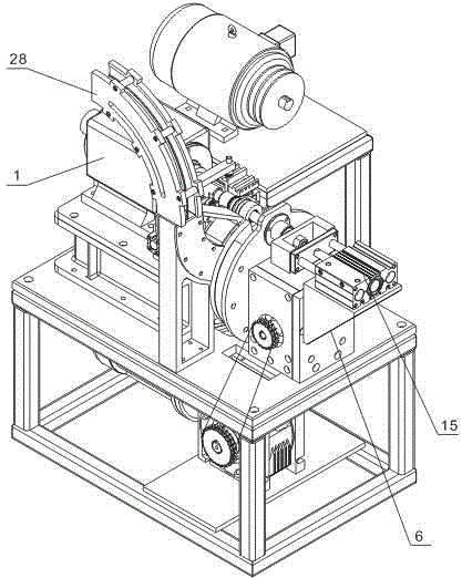
[0058] Such as Figure 1~Figure 5 As shown, the crimping and cutting device includes a driving motor 1; also includes a crimping wheel 2 and a cutter 3 arranged on both sides of the output shaft of the driving motor 1; direction, the driving structure A that drives the cutter 3 to move in the axial direction of the output shaft of the drive motor 1; also includes a workpiece positioning plate 4, and the edge of the workpiece positioning plate 4 is uniformly provided with a plurality of through holes 5; also includes a cam The splitter 6, the output shaft of the cam splitter 6 is connected to the workpiece positioning plate 4, and the cam splitter 6 is configured so that the input shaft rotates one revolution, and the output shaft drives the workpiece positioning plate 4 to rotate at a certain angle to make the workpiece positioning plate 4 rotate. One is facing the output shaft of the drive motor 1 through the hole 5; it also includes a push rod 7 facing the output shaft of th...

Embodiment 2

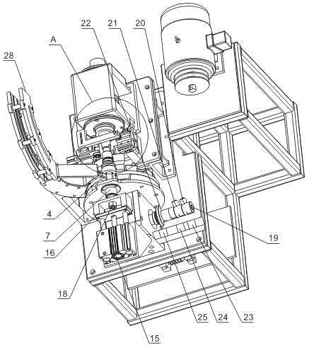
[0066] Such as figure 2 and Figure 5 As shown, this embodiment further describes the cam control device on the basis of embodiment 1. The cam control device includes a control shaft 19 connected to the output shaft of the cam splitter 6, and is arranged on the control shaft 19. The first control cam 20, the second control cam 21 and the third control cam 22, the first proximity sensor 23 and the second proximity sensor corresponding to the first control cam 20, the second control cam 21 and the third control cam 22 respectively 24 and the third proximity sensor 25, the first electric control valve, the second electric control valve and the third electric control valve connected with the first proximity sensor 23, the second proximity sensor 24 and the third proximity sensor 25 respectively, the first electric control valve The control valve is connected with the drive structure A, and the second electric control valve and the third electric control valve are connected with ...

Embodiment 3

[0078] Such as Figure 1~Figure 5 As shown, this embodiment further describes the driving structure A on the basis of the second embodiment.

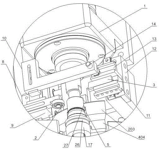
[0079] Described driving structure A comprises cylinder A8, crimping wheel fixed body 9, connecting body 10 and cutter fixed body 11, and the output shaft of cylinder A8 is perpendicular to the output shaft of described drive motor 1, and the output shaft of cylinder A8 and curling The wheel fixed body 9 is connected, and the two ends of the connecting body 10 are connected with the crimping wheel fixed body 9 and the cutter fixed body 11 respectively, and the crimping wheel 2 is fixed on the crimping wheel fixed body 9, and the cutter 3 is fixed On the cutter fixed body 11;

[0080] The drive structure A also includes a sliding fixed block 12, on which the cutter fixed body 11 is slidably arranged, and the sliding direction of the cutter fixed body 11 is parallel to the output shaft of the drive motor 1;

[0081] A chute 13 is provid...


PUM


Abstract

The invention discloses a hemming notch cutting device which comprises a driving motor, a hemming wheel, a cutter, a driving structure A for driving the hemming wheel to move in the radial direction of the output shaft of the driving motor to drive the cutter to move in the axial direction of the output shaft of the driving motor, a workpiece locating disc, a cam divider with an output shaft connected with the workpiece locating disc, a mandril right opposite to the output shaft of the driving motor, a driving structure B for sucking workpieces and driving the mandril to move in the axis direction and a cam control device for controlling the driving structure A and the driving structure B to work, wherein the hemming wheel and the cutter are arranged on two sides of an output shaft of the driving motor. The invention further discloses a hemming notch cutting method. The device and method has the advantages of being high in efficiency, stable in product quality and low in rejection rate compared with traditional manual operation.

Description

technical field [0001] The invention relates to a device and method for automatic curling and cutting of workpieces. Background technique [0002] At present, the bottle caps of beverage bottles and wine bottles on the market mostly adopt a double-layer structure, including an inner cap connected to the bottle body and an outer cap arranged on the outer surface of the inner cap for decoration or identification. [0003] After the outer cover is pressed onto the inner cover, the excessively long edge of the open end of the outer cover needs to be cut off, and at the same time, the open end of the outer cover needs to be crimped to prevent the open end of the outer cover from scratching the user. [0004] At present, the process of cutting and crimping bottle caps is done manually, which is not only inefficient, but also the product quality is extremely unstable and the scrap rate is high. [0005] At present, the art lacks a device and method capable of automatically cutting...

Claims


Application Information

Patent Timeline
Patent Type & Authority Patents(China)
IPC IPC(8): B23P23/02B23Q5/22B23Q5/02B23Q3/00B23Q7/00
CPCB23P23/04B23Q5/00B23Q7/02
Inventor 税刚
Owner SICHUAN XINGDA PACKAGING EQUIP MFG
Why Eureka
Try Eureka