
Automotive carpet radiant heating system

A technology for automotive carpet and radiant heating, applied in vehicle components, heating/cooling equipment, air handling equipment, etc., can solve problems such as uneven air temperature distribution, poor comfort, and low ambient air temperature increase, to prevent heat consumption. , temperature balance, improve the effect of heating efficiency

Active Publication Date: 2014-03-19
CHONGQING CHANGAN AUTOMOBILE CO LTD
View PDF9 Cites 12 Cited by
  • Summary
  • Abstract
  • Description
  • Claims
  • Application Information

AI Technical Summary

Problems solved by technology

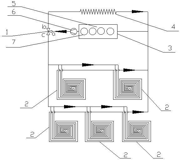
The floor heating radiators in each group are arranged in series, such as the five floor heating radiators described in the specific embodiment section, wherein two of the front row are connected in series, three of the rear row are connected in series, and the front row and the rear row are connected in parallel. The floor heating radiators and the rear floor heating radiators are all connected in series, so the average surface temperature of each floor heating radiator along the coolant flow direction decreases successively, and the temperature difference between the floor heating radiator surface and the air in the cabin becomes smaller and smaller. The heat that the floor heating radiator can transfer to the air is getting less and less, and the temperature increase of the surrounding air is getting lower and lower, making the air temperature on the left side of the front row and the rear row higher than the air temperature on the right side, and the air in the cabin Uneven temperature distribution and poor comfort

Method used


Image

  • Automotive carpet radiant heating system
  • Automotive carpet radiant heating system
  • Automotive carpet radiant heating system

Examples


Embodiment Construction

[0015] The present invention will be further described below in conjunction with accompanying drawing.

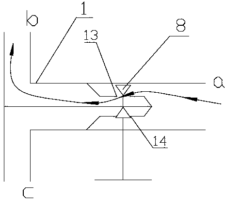
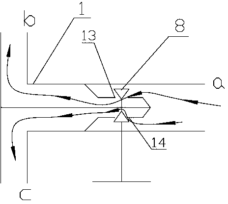
[0016] Such as Figure 1 to Figure 4 The car carpet radiant heating system shown includes a car carpet, a body floor, an engine cooling system, a flow regulating valve 1 and five coil radiators 2, and the engine cooling system includes an engine 3 (which has a cylinder 7 and a water jacket 5), radiator 4 and water pump 6, the water inlet of the water pump 6 is connected to the coolant outlet of the engine 3 through a pipeline, and five coil radiators 2 are arranged in parallel between the car carpet and the vehicle body floor (the coil radiator 2 and the vehicle body floor There is a heat insulation layer on the contact surface), two coil radiators 2 are connected in parallel in the front row, and three coil radiators 2 are connected in parallel in the rear row. The coil radiator 2 adopts floor heating coils, and each coil radiator 2 All have a first water inlet pipe 9, a ...


PUM


Abstract

The invention discloses an automotive carpet radiant heating system. The automotive carpet radiant heating system comprises an automotive carpet, an automobile body floor, an engine cooling system, a flow regulating valve and a plurality of coiled radiators, wherein the engine cooling system comprises an engine, a radiator and a water pump; a water inlet of the water pump is connected to a coolant outlet of the engine through a pipeline, the plurality of coiled radiators are connected in parallel and arranged between the automotive carpet and the automobile body floor, an inlet of the flow regulating valve is connected to a water outlet of the water pump through a pipeline, a first outlet of the flow regulating valve is connected to a water inlet of the radiator through a pipeline, a water outlet of the radiator is connected to a coolant inlet of the engine through a pipeline, a second outlet of the flow regulating valve is connected to water inlets of the plurality of coiled radiators through pipelines, and water outlets of the plurality of coiled radiators are connected to the coolant inlet of the engine through pipelines. By means of the heating system, the temperature of the automotive carpet can be balanced, so that the temperature of the air in a carriage is evenly distributed, and the comfort is improved.

Description

technical field [0001] The invention belongs to the field of automobiles, and in particular relates to an automobile carpet radiation heating system. Background technique [0002] Car carpet radiant heating is a method of introducing the coolant flowing out of the engine cooling system into the coil radiator installed between the car carpet and the floor of the car body to circulate, heat the entire car carpet, and evenly radiate heat into the cabin through the car carpet. Heating method. Compared with the traditional HVAC heating method, it has the following advantages: (1) The blower, air outlet, and air duct are canceled, which not only eliminates noise, but also reduces power consumption, and also simplifies the volume of the air-conditioning box; (2 )Using the uniform thermal radiation on the surface of the entire car carpet as a heat dissipation source, the heat radiates upward from the bottom to heat the air in the compartment, and the temperature of the car carpet ...

Claims


Application Information

Patent Timeline
IPC IPC(8): B60H1/06
CPCB60H1/00295B60H2001/00307
Inventor 蔡操平孟锐
Owner CHONGQING CHANGAN AUTOMOBILE CO LTD
Learn More