Eureka AIR delivers breakthrough ideas for toughest innovation challenges, trusted by R&D personnel around the world.

Oil charge and discharge control valve for coupler

A technology of oil discharge control and coupling, applied in the direction of valve details, multi-way valves, valve devices, etc., can solve the problems of high motor failure rate, complex structure, high failure rate, etc., to ensure the oil pressure balance of the system and the overall structure is simple , the effect of simple control

Inactive Publication Date: 2014-03-19
CRRC QINGDAO SIFANG CO LTD
View PDF4 Cites 5 Cited by
  • Summary
  • Abstract
  • Description
  • Claims
  • Application Information

AI Technical Summary

Problems solved by technology

[0002] At present, high-power internal combustion engines are generally equipped with cooling fans, that is, when the internal combustion engine is started, the cooling fan is started immediately. In the prior art, the cooling fan generally has the following two driving methods, one is motor drive, and the motor directly drives the cooling fan. However, the failure rate of the motor is high, and the cost is high, which is greatly affected by the vehicle operating environment and climate; the other is driven by the hydrostatic system, which uses the hydrostatic pump and the hydrostatic system to control the hydrostatic motor, and then the hydrostatic motor Drive the cooling fan, but the drive system has complicated pipelines, many auxiliary equipment, and high failure rate
At present, there are also hydraulic couplings used to transmit torque to drive the cooling fan, and the work of the hydraulic coupling is controlled by controlling the oil filling, oil discharge and liquid filling rate of the coupling, thereby realizing the opening, stopping and adjustment of the cooling fan. High-speed automatic operation, but in the prior art, the control method of the cooling fan is relatively complicated, and the structure of the oil filling and discharging control valve used to control the oil filling and discharging of the coupling is also relatively complicated.

Method used


Image

  • Oil charge and discharge control valve for coupler
  • Oil charge and discharge control valve for coupler

Examples


Embodiment Construction

[0019] Below in conjunction with accompanying drawing and specific embodiment the present invention is described in further detail:

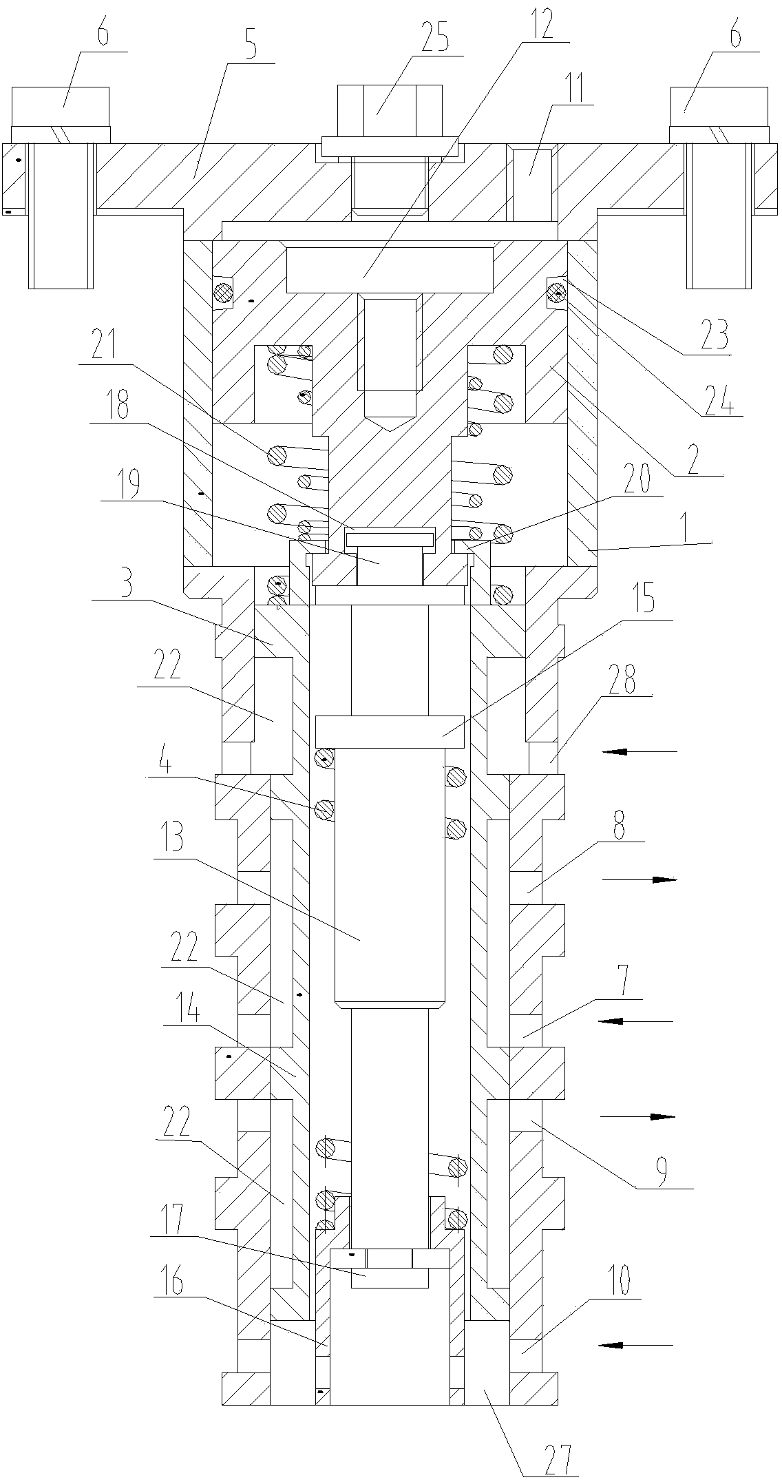
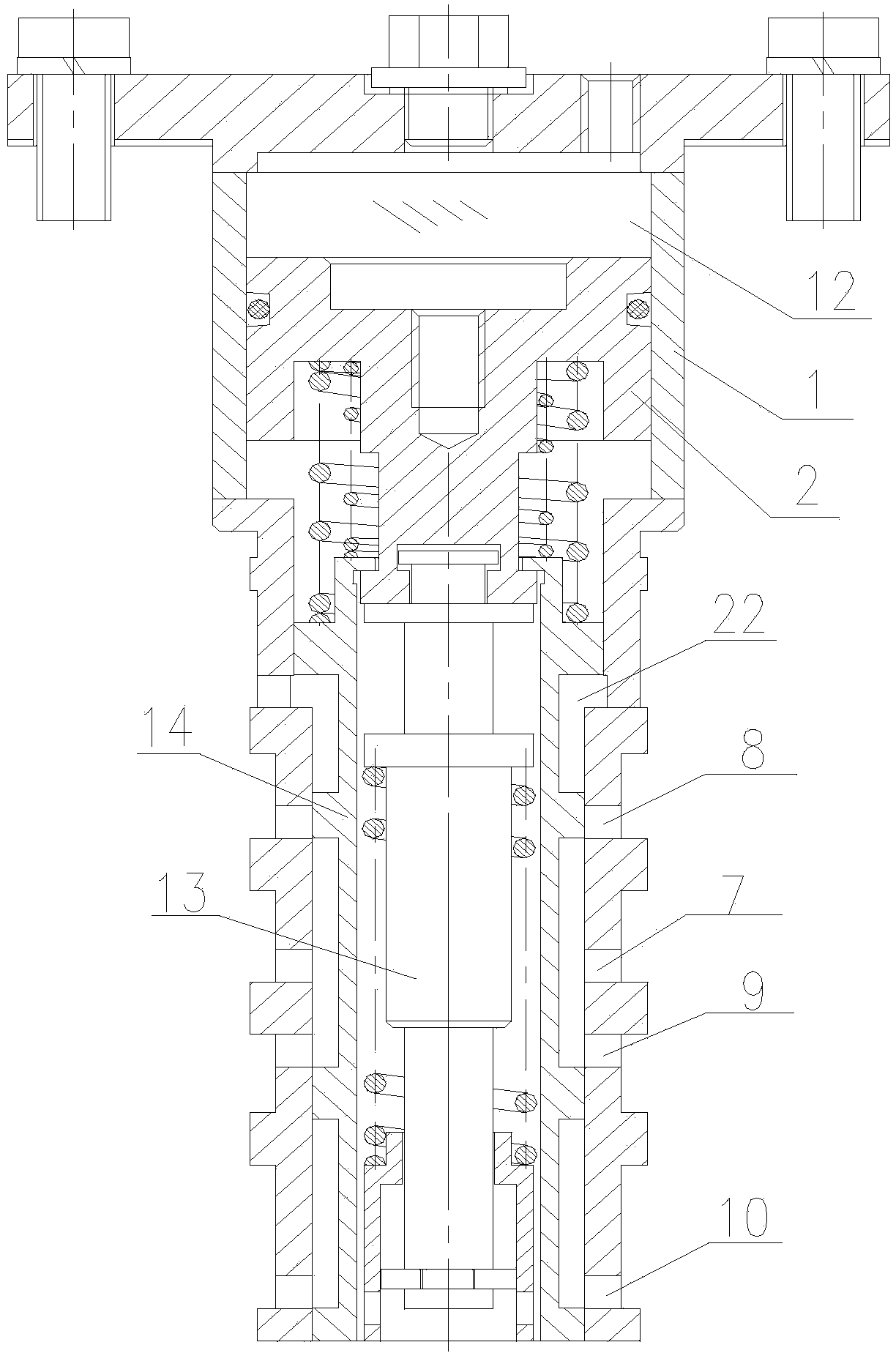
[0020] Such as figure 1 and figure 2 As shown, a coupling oil filling and discharging control valve provided by the present invention includes a valve body 1, and the valve body 1 is fixed on the control valve mounting seat of the coupling (not shown in the figure), and the valve body 1 is provided with Piston 2, control spool 3 and return spring 4, the bottom of piston 2 is connected to the top of control spool 3, piston 2 drives control spool 3 to move, piston 2, control spool 3 and the inner wall of valve body 1 slide connect. There is a detachable gland 5 on the top of the valve body 1 , the gland 5 compresses the valve body 1 and is fixedly connected to the control valve mounting seat by bolts 6 .

[0021] The valve body 1 is provided with an oil inlet 7 and an oil return port 8 connected with the coupling, an oil filling port 9 connect...


PUM


Abstract

The invention relates to an oil charge and discharge control valve for a coupler. The oil charge and discharge control valve comprises a valve body, an oil inlet, an oil return port, an oil charge port, an oil discharge port and an air inlet of high-pressure air are formed in the valve body, the oil inlet and the oil return port are connected with an oil tank, the oil charge port is connected with the coupler, the oil discharge port is connected with an oil discharge groove of the coupler, a piston, a control slide valve and a resetting spring are arranged in the valve body, an air chamber is formed in the top of the piston, the air inlet is communicated with the air chamber, the piston is connected with the top of the control slide valve, the resetting spring is connected to the control slide valve, the piston and the control slide valve are in sliding connection with the inner wall of the valve body, and the oil inlet, the oil return port, the oil charge port and the oil discharge port are selectively communicated or disconnected through the movement of the control slide valve. The overall structure of the oil charge and discharge control valve is simple, work oil flows continuously in a circulating mode in the work process, system oil pressure can be balanced, a liquid coupler is made to work stably and reliably, it is guaranteed that a cooling fan only rotates at two rotating speeds of rated speed and running-down speed, and the control mode of the cooling fan is simpler.

Description

technical field [0001] The invention relates to a coupling used for driving a cooling fan of an internal combustion engine, in particular to a coupling oil filling and discharging control valve for controlling the oil filling and discharging work of the coupling. Background technique [0002] At present, high-power internal combustion engines are generally equipped with cooling fans, that is, when the internal combustion engine is started, the cooling fan is started immediately. In the prior art, the cooling fan generally has the following two drive methods, one is motor drive, and the motor directly drives the cooling fan. However, the failure rate of the motor is high, and the cost is high, which is greatly affected by the vehicle operating environment and climate; the other is driven by the hydrostatic system, which uses the hydrostatic pump and the hydrostatic system to control the hydrostatic motor, and then the hydrostatic motor Drive the cooling fan, but the drive sys...

Claims


Application Information

Patent Timeline
Patent Type & Authority Applications(China)
IPC IPC(8): F16K11/07F16H41/24
CPCF16K11/07F16H41/24F16K27/041
Inventor 弓海斌孙瑞袁博丁叁叁梁建英龚明
Owner CRRC QINGDAO SIFANG CO LTD
Why Eureka
Eureka Blog
Learn More