Ionizing sensor based on discharge electric field with micro-gap polarization structure

A technology of structural structure and sensor, applied in instruments, scientific instruments, material analysis by electromagnetic means, etc., can solve the problems of high random signal components, difficult materials with large aspect ratio, and small sampling space, etc., to improve the signal-to-noise ratio. and sensitivity, reducing the probability of contamination failure, and increasing the effect of sampling space

Active Publication Date: 2014-03-19
SHANGHAI JIAO TONG UNIV
View PDF4 Cites 8 Cited by
  • Summary
  • Abstract
  • Description
  • Claims
  • Application Information

AI Technical Summary

Problems solved by technology

Its technical limitations are: first, the Pylux glass used as electrode gap adjustment is as thick as 500 microns, and the working voltage is too high; second, the micropore air intake sampling is still a small air intake area sampling
[0012] Therefore, the micron-scale small-scale discharge gap technology solution brings the problems of narrow sampling space, excessively high random component of the signal, and decreased signal-to-noise ratio
At the same time, it also makes it difficult for materials with large aspect ratios to be placed on electrode pairs with small gaps while avoiding short circuits.
More importantly, this electrode structure is easily contaminated by suspended matter such as dust or fibers in the air, resulting in device failure, which greatly limits its application fields.

Method used


Image

  • Ionizing sensor based on discharge electric field with micro-gap polarization structure
  • Ionizing sensor based on discharge electric field with micro-gap polarization structure
  • Ionizing sensor based on discharge electric field with micro-gap polarization structure

Examples


Embodiment 1

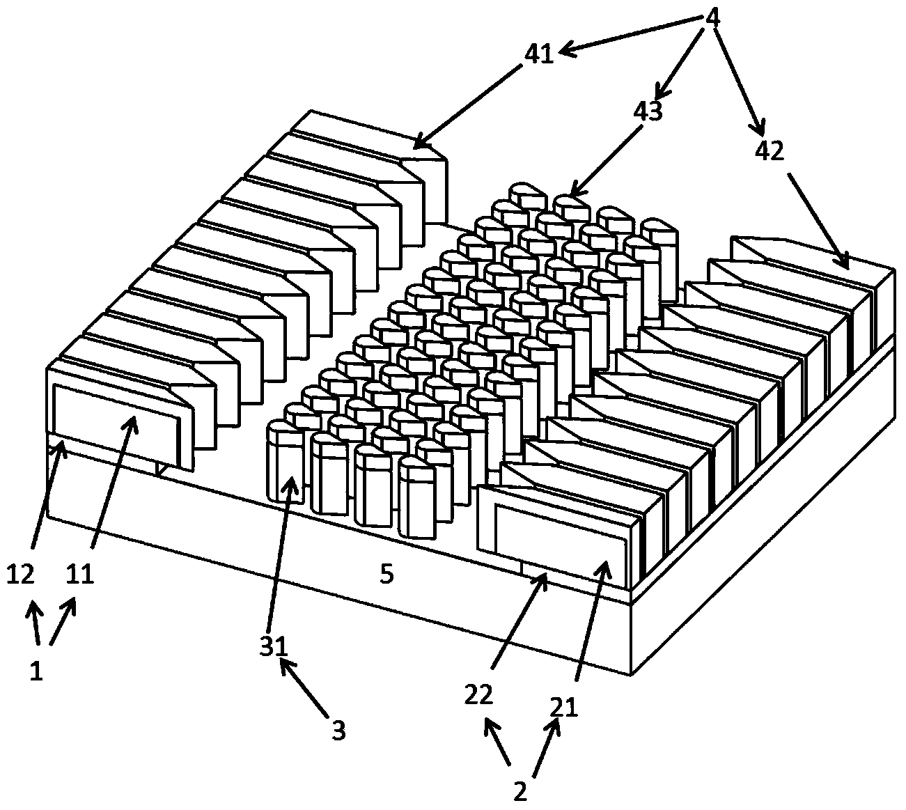
[0063] Such as figure 1 As shown, an ionization sensor that constructs a discharge electric field based on a micro-gap polarization structure includes: a copper first external circuit electrode 1, a copper second external circuit electrode 2, a copper polarization structure 3, and a large aspect ratio Material 4 and glass substrate 5; wherein, the polarization structure 3 is arranged between the first external circuit electrode 1 and the second external circuit electrode 2, and the large aspect ratio material 4 is arranged between the first external circuit electrode 1 and the second external circuit electrode The entire surface of the electrode 2 is disposed on a part of the surface of the polarized structure 3 ; the first external circuit electrode 1 , the second external circuit electrode 2 and the polarized structure 3 are disposed on the substrate 5 .

[0064] Between the first external circuit electrode 1 and the polarized structure 3, there is a gas gap of 50 microns, b...

Embodiment 2

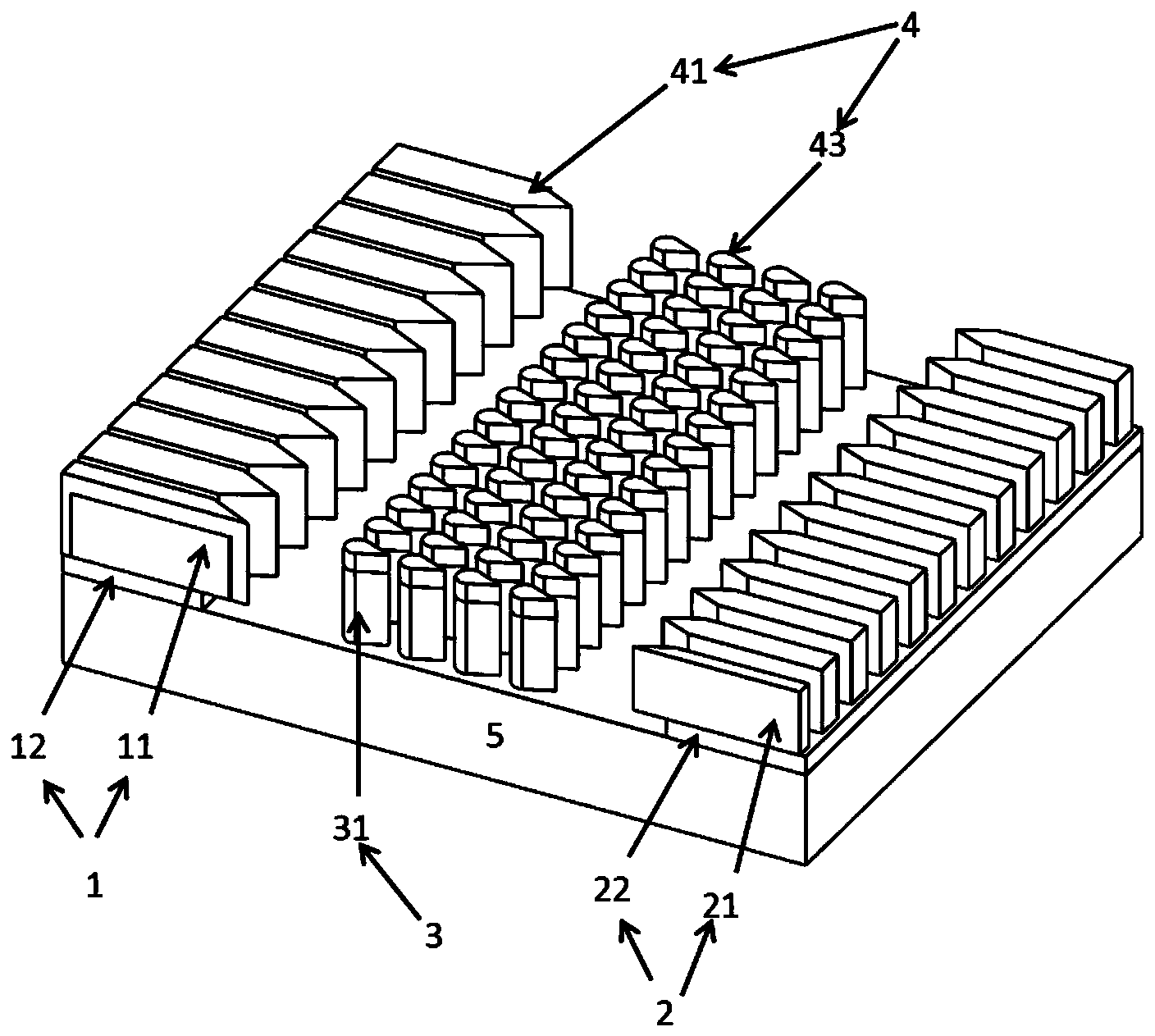
[0080] Such as figure 2 As shown, the technical solution of this embodiment is the same as that of Embodiment 1 except for the following features: the large aspect ratio material 4 is arranged on the entire surface of the first external circuit electrode 1 and is arranged on a part of the surface of the polarized structure 3, Specifically, it is the upper surface and the upper part of the side wall of each structural unit 31 of the polarization structure 3 , and is not arranged on the surface of the second external circuit electrode 2 . In the sensor of this embodiment, the large aspect ratio material 4 is not arranged on the surface of the second external circuit electrode 2, and the present invention does not require the electrode pair and the polarization structure to be provided with a large aspect ratio material, so it is easier to process, and The problem of short circuit is not easy to occur, and it is beneficial to improve the yield and stability of the device.

[00...

Embodiment 3

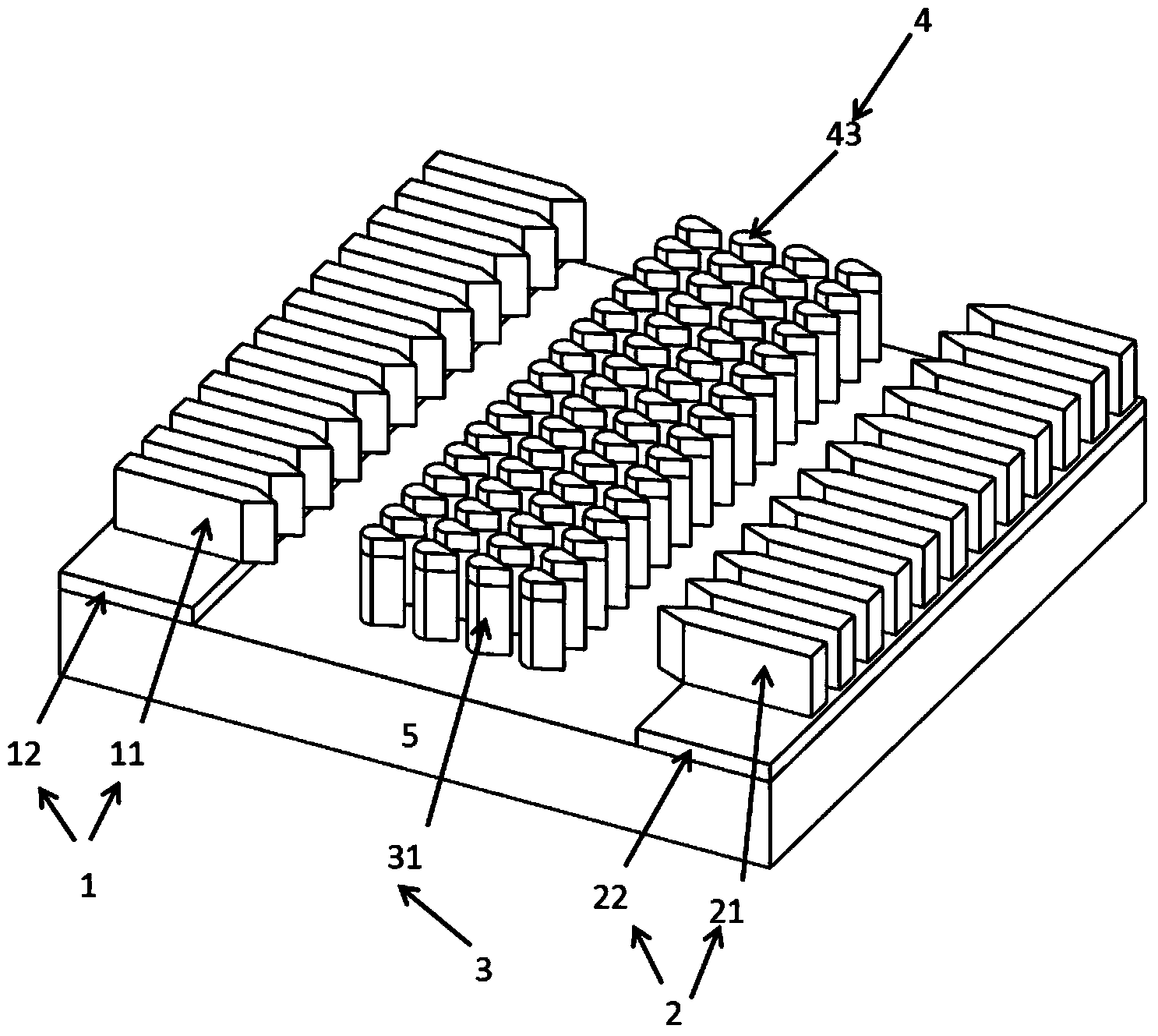
[0084] Such as image 3 As shown, the technical solution of this embodiment is the same as that of Embodiment 1 except for the following features: the large aspect ratio material 4 is not arranged on the surface of the first external circuit electrode 1 and the second external circuit electrode 2, but only on the electrodes. part of the surface of structure 3.

[0085] In the sensor of this embodiment, it is only arranged on a part of the surface of the polarized structure 3, and the present invention does not require materials with a large aspect ratio to be arranged on the electrode pairs and the polarized structure, nor does it require to be arranged on all of the electrode pairs or the polarized structure. surface and thus easier to process.

[0086] The first external circuit electrode 1 and the second external circuit electrode 2 of the sensor are respectively connected to the test terminal positive pole and negative pole of the Agilent B2911A volt-ampere characteristic...


PUM

PropertyMeasurementUnit
diameteraaaaaaaaaa
aspect ratioaaaaaaaaaa
diameteraaaaaaaaaa

Abstract

The invention discloses an ionizing gas sensor based on a discharge electric field with a micro-gap polarization structure. The ionizing gas sensor comprises an external circuit electrode couple, the polarization structure and a material with a large length-diameter ratio, wherein the polarization structure is arranged at the area between the external circuit electrode couple; and the material with large length-diameter ratio is at least arranged on one of the polarization structure and the external circuit electrode couple. When the ionizing gas sensor works, lower voltage is only needed to be loaded onto electrodes of an external circuit, and the electric field which is enough to ionize target gas molecules is generated between the polarization structure and the electrodes of the external circuit by the polarization action of the polarization structure, so that the working voltage of the sensor is effectively reduced. Compared with the micro-gap structure between the external circuit electrode couple in the prior art, the ionizing gas sensor effectively solves the problems of instability and failure caused by contaminants such as dust, fiber and the like which fall into a micro-gap, and the signal to noise ratio and the sensitiveness are improved.

Description

technical field [0001] The invention relates to an ionization sensor, in particular to an ionization sensor which constructs a discharge electric field based on a micro-gap polarization structure. Background technique [0002] Ionization gas sensor realizes sensing through the gas electronic signal generated by the ionization of gas molecules. Its main advantages are fast response, short response time and wide sensitive range. It is an important supplement to other types of sensors. It is used in dangerous gas alarm, It has important application prospects in many fields such as toxic and harmful gas monitoring. [0003] However, in order to ionize gas molecules, a high electric field needs to be applied, thus, high voltage operation becomes a common bottleneck problem for this type of sensor. [0004] A literature search of the prior art found that in the published technical literature, in order to solve this bottleneck problem, it is mainly to cover the electrode surface w...

Claims


Application Information

Patent Timeline
Patent Type & Authority Applications(China)
IPC IPC(8): G01N27/70
Inventor 侯中宇房茂波王孜王艳芳赵小林
Owner SHANGHAI JIAO TONG UNIV
Why Eureka
Try Eureka