Low-axial-ratio broadband circularly polarized micro-strip antenna

A technology of microstrip antenna and circular polarization, which is applied in the field of broadband circularly polarized microstrip antenna and circularly polarized microstrip antenna, which can solve the problems of poor axial ratio characteristics and narrow frequency band of microstrip circularly polarized antenna. Achieve low axial ratio, excellent circular polarization characteristics, and increase the effect of applicable situations

Inactive Publication Date: 2014-03-19
HARBIN INST OF TECH
View PDF2 Cites 2 Cited by
  • Summary
  • Abstract
  • Description
  • Claims
  • Application Information

AI Technical Summary

Problems solved by technology

[0003] In order to solve the problems of narrow frequency band and poor axial ratio characteristics of traditional microstrip circularly polarized antennas, the present invention proposes a broadband circularly polarized microstrip antenna with low axial ratio

Method used


Image

  • Low-axial-ratio broadband circularly polarized micro-strip antenna
  • Low-axial-ratio broadband circularly polarized micro-strip antenna
  • Low-axial-ratio broadband circularly polarized micro-strip antenna

Examples


specific Embodiment approach 1

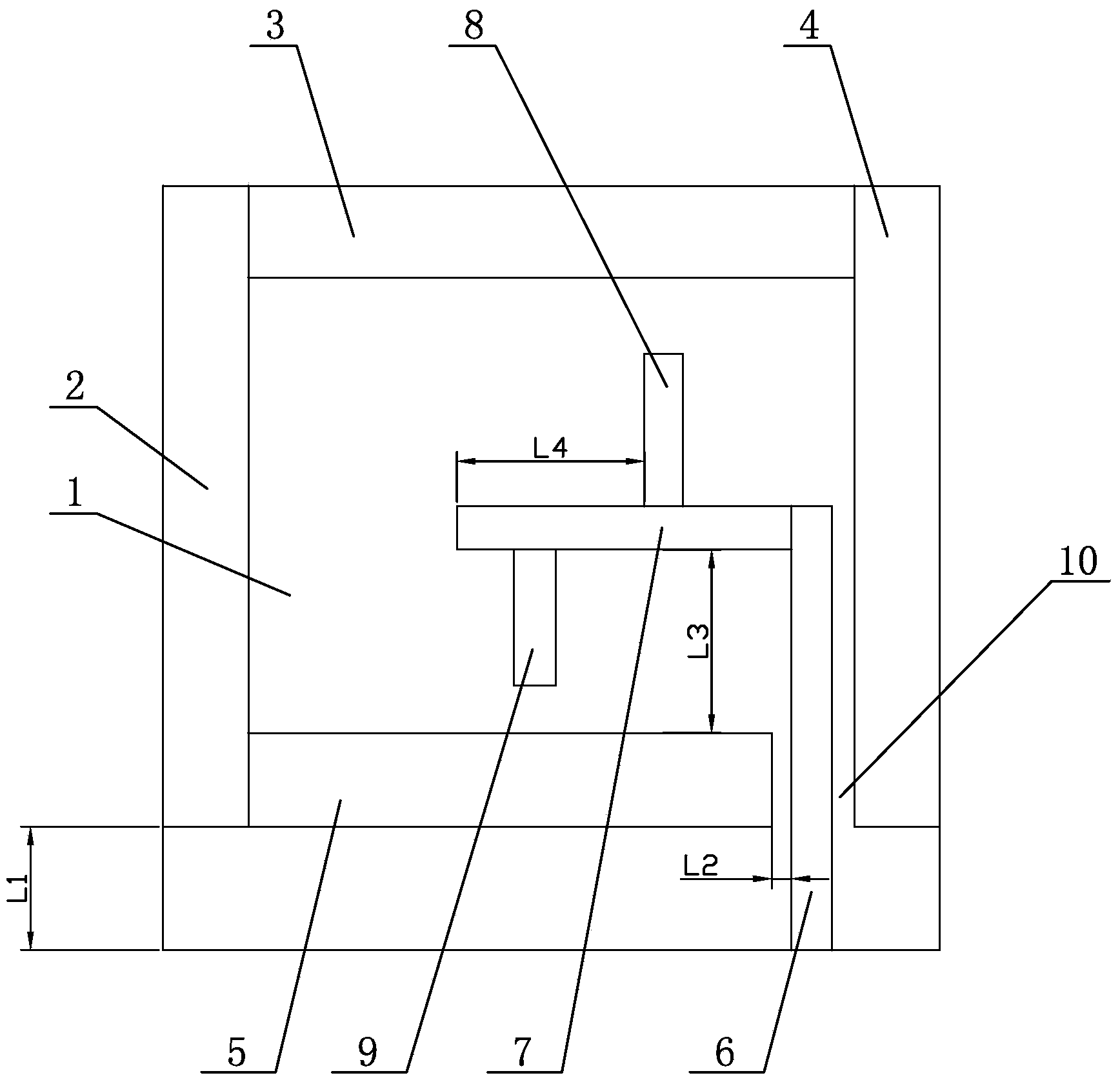
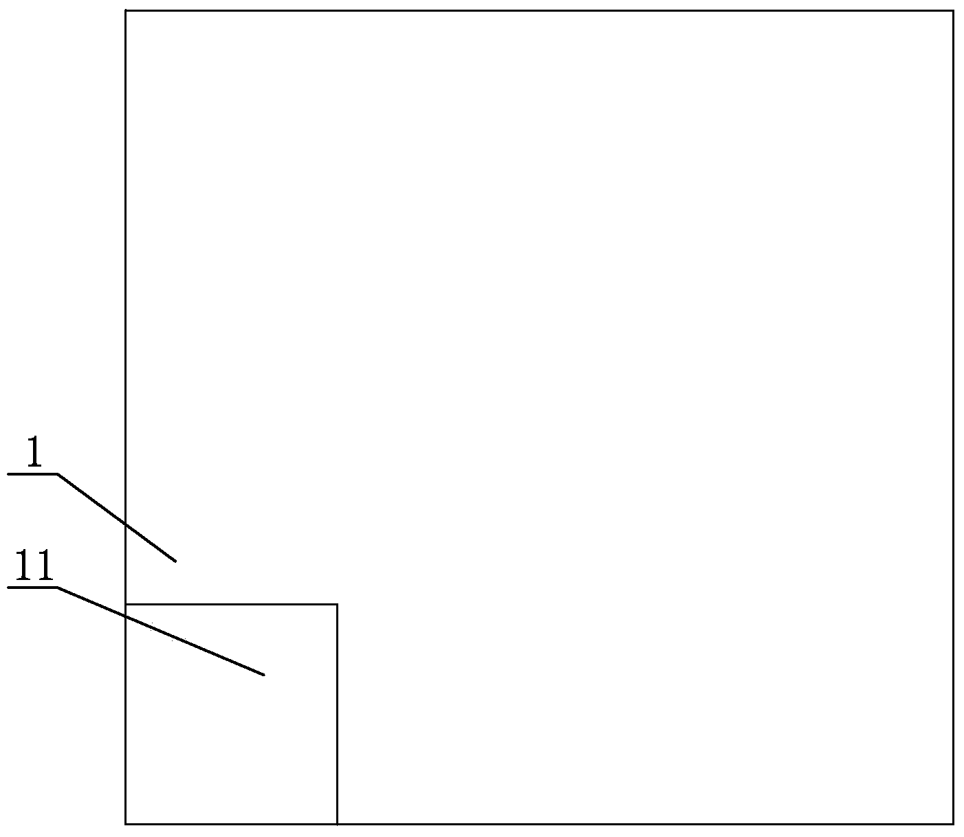
[0011] Specific implementation mode one: combine Figure 1 to Figure 10 Describe this embodiment, the wideband circularly polarized microstrip antenna with low axial ratio described in this embodiment includes a dielectric plate 1, a first upper metal strip 2, a second upper metal strip 3, a third upper metal strip 4, The fourth upper metal strip 5, the fifth upper metal strip 6, the sixth upper metal strip 7, the seventh upper metal strip 8, the eighth upper metal strip 9 and the lower metal strip 10, the medium plate 1 is Rectangular plate body, the first upper layer metal strip 2 is printed along the side edge of the front side of the medium board 1, and the upper end of the first upper layer metal strip 2 is connected to the upper edge of the front side of the medium plate 1, and the third upper layer metal strip 4 is printed along the side edge of the medium plate 1. The edge of the other side of the front side of the plate 1 is printed, and the upper end of the third upp...

specific Embodiment approach 2

[0013] Specific implementation mode two: combination figure 1 with figure 2 To describe this embodiment, the thickness of the dielectric plate 1 of the broadband circularly polarized microstrip antenna with low axial ratio in this embodiment is 1.5 mm, and the dielectric constant of the dielectric plate 1 is 4.4.

[0014] The technical effect of this embodiment is that: with such an arrangement, the manufacturing cost of the antenna can be very low, which is convenient for practical application. We can directly choose the FR4 board to make the antenna. Other components and connections are the same as those in the first embodiment.

specific Embodiment approach 3

[0015] Specific implementation mode three: combination figure 1 with figure 2 Describe this embodiment, the first upper layer metal strip 2, the second upper layer metal strip 3, the third upper layer metal strip 4, the fourth upper layer metal The thickness of strip 5, the fifth upper layer metal strip 6, the sixth upper layer metal strip 7, the seventh upper layer metal strip 8, the eighth upper layer metal strip 9, and the lower layer metal strip 10 are all 0.1mm, the first The length of the upper metal strip 2 is 62.8mm, the width of the first upper metal strip 2 is 5.45mm, the length of the second upper metal strip 3 is 62.8mm, and the width of the second upper metal strip 3 is 5.45mm, The length of the 3rd upper metal strip 4 is, the width of the 3rd upper metal strip 4 is , the length of the 4th upper metal strip 5 is 62.8mm, the width of the 4th upper metal strip 5 is 5.45mm, the fifth The length of the upper metal strip 6 is 36.45mm, the width of the fifth upper me...


PUM


Abstract

The invention relates to a band circularly polarized micro-strip antenna and in particular relates to a low-axial-ratio broadband circularly polarized micro-strip antenna, aiming at solving the problems that a traditional circularly polarized micro-strip antenna is narrow in frequency band and poor in axial ratio characteristics. A first upper-layer metal strip is printed along the edge on one side of the front side of a dielectric slab; a third upper-layer metal strip is printed on the edge on the other side of the front side of the dielectric slab; a second upper-layer metal strip is printed along the edge on the dielectric slab; a fourth upper-layer metal strip is printed on the lower part of the front side of the dielectric slab; a fifth upper-layer metal strip is printed in a gap; a sixth upper-layer metal strip is printed in the middle of the front side of the dielectric slab; a seventh upper-layer metal strip is printed above the sixth upper-layer metal strip on the front side of the dielectric slab; an eighth upper-layer metal strip is printed below the sixth upper-layer metal strip on the front side of the dielectric slab; a lower-layer metal strip is printed at the bottom on the back of the dielectric slab. The low-axial-ratio broadband circularly polarized micro-strip antenna is applied to the field of radio communication.

Description

technical field [0001] The invention relates to a circularly polarized microstrip antenna, in particular to a low-axis ratio broadband circularly polarized microstrip antenna, which belongs to the field of radio communication. Background technique [0002] With the rapid development of modern electronic information technology and the increasing application of radio equipment, antennas, as a device for energy conversion and directional radiation and reception of electromagnetic waves, have received widespread attention and in-depth research. As the front-end component of wireless communication equipment, the antenna plays a vital role in the performance of the communication system. Therefore, it is very important to design high-performance antennas that can meet the specific requirements of current diversified communication systems. Since G.A.Deschamps proposed the concept of microstrip radiators in 1953, due to the development of microwave integration technology and the urg...

Claims


Application Information

Patent Timeline
Patent Type & Authority Applications(China)
IPC IPC(8): H01Q21/24H01Q1/38H01Q1/50H01Q13/08
Inventor 祁嘉然韩崇志林澍邱景辉罗晓特尼格尔
Owner HARBIN INST OF TECH
Why Eureka
Try Eureka