Driving motor and series-parallel hybrid power system
A technology for driving motors and brakes, which is applied to the arrangement of multiple different prime movers of power units, pneumatic power units, and general power units, etc., can solve the problems of restrictions on the installation and use of drive motors, increase in size and weight of drive motors, etc. Achieve improved range of use, overall size and weight reduction, size and weight reduction
- Summary
- Abstract
- Description
- Claims
- Application Information
AI Technical Summary
Problems solved by technology
Method used
Image
Examples
Embodiment 1
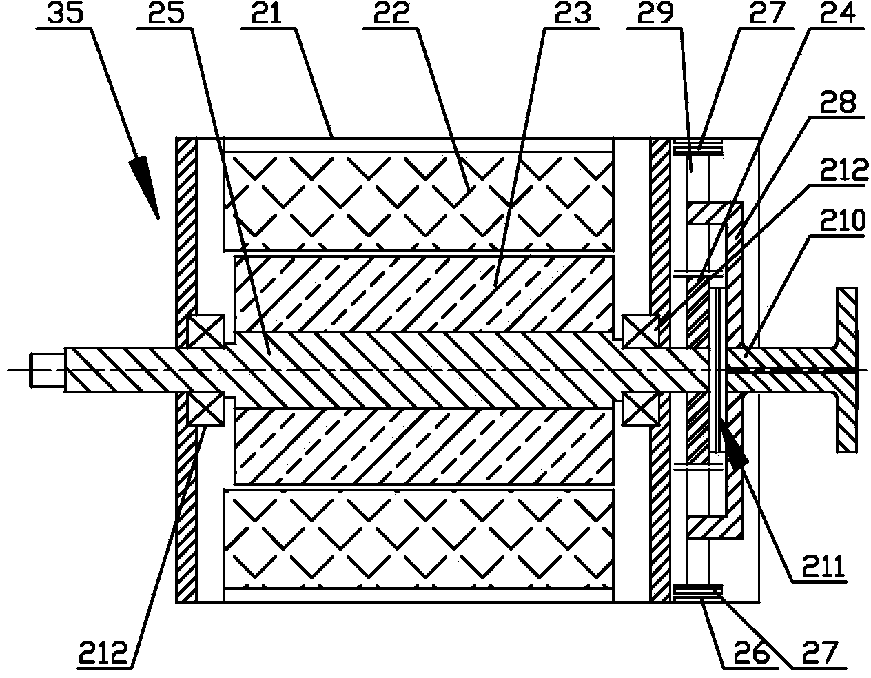
[0042] Such as figure 2As shown, the driving motor 35 provided in this embodiment includes a housing 21 and a stator 22 and a rotor 23 placed in the housing 21; the middle part of the rotor 23 is formed with a rotor shaft for socketing and fixing the sun gear 24 25. The inside of the housing 21 is equipped with an inner ring gear 27 through the first brake 26. The sun gear 24 and the inner ring gear 27 are both meshed with the planetary gear 29 installed on the planet carrier 28. The middle part of the planet carrier 28 is aligned with the The set output connection shaft 210 is fixedly connected, and a second brake 211 is arranged between the planet carrier 28 and the sun gear 24; wherein, the coupling or separation between the ring gear 27 and the housing 21 is realized through the first brake 26, and the sun gear 24 and the planetary carrier 28 are connected or separated through the second brake 211 .
[0043] During use, when the automobile is running at a low speed, the ...
Embodiment 2
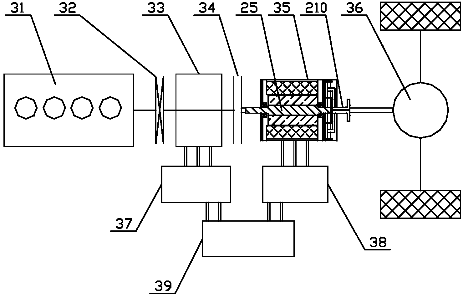
[0055] Such as image 3 As shown, the series hybrid system provided in this embodiment includes an engine 31 and a torsional damper 32 and a generator 33 arranged on the output shaft of the engine 31 in sequence, and the output shaft of the engine 31 and the clutch 34 The input end is connected; the output end of the clutch 34 is connected with the input end of the rotor shaft 25 in the drive motor 35 described in the above-mentioned embodiment one, and the output end of the output connection shaft 210 in the drive motor 35 is connected with the drive axle 36; The motor 33 is connected with the energy storage device 39 through the first motor controller 37 , and the drive motor 35 is connected with the energy storage device 39 through the second motor controller 38 .
[0056] It should be noted that the engine 31, the torsional shock absorber 32 and the generator 33 are not necessarily connected sequentially through a main shaft, but can also be connected in sequence through s...
Embodiment 3
[0065] Such as Figure 4 As shown, the series hybrid system provided in this embodiment includes an engine 31 and a clutch 34 whose input end is connected to the output shaft of the engine 31. The output end of the clutch 34 is connected to the drive motor 35 described in the first embodiment above. The input end of the rotor shaft 25 in the drive motor 35 is connected to the input end, and the output end of the output connection shaft 210 in the drive motor 35 is connected to the drive axle 36; the output shaft of the engine 31 is connected to the generator 33 through the transmission device 310; the generator 33 is connected to the generator through the first motor The controller 37 is connected with the energy storage device 39 , and the driving motor 35 is connected with the energy storage device 39 through the second motor controller 38 .
[0066] The overall structure of the hybrid hybrid system provided in this embodiment is similar to the hybrid hybrid system provided ...
PUM
 Abstract
Description
Claims
Application Information
 - R&D
- Intellectual Property
- Life Sciences
- Materials
- Tech Scout
- Unparalleled Data Quality
- Higher Quality Content
- 60% Fewer Hallucinations
Browse by: Latest US Patents, China's latest patents, Technical Efficacy Thesaurus, Application Domain, Technology Topic, Popular Technical Reports.
© 2025 PatSnap. All rights reserved.Legal|Privacy policy|Modern Slavery Act Transparency Statement|Sitemap|About US| Contact US: help@patsnap.com


