Vacuum film forming device

一种成膜装置、真空的技术,应用在真空蒸发镀覆、离子注入镀覆、气态化学镀覆等方向,能够解决成膜速度降低、难以控制电弧放电弧斑的位置、生产性降低等问题

Inactive Publication Date: 2016-03-23
KOBE STEEL LTD
View PDF10 Cites 0 Cited by
  • Summary
  • Abstract
  • Description
  • Claims
  • Application Information

AI Technical Summary

Problems solved by technology

Therefore, the opportunity to carry out the film-forming process with a full load of substrates in the vacuum chamber of the physical deposition apparatus is reduced, and the productivity is reduced.
[0013] In addition, in the AIP device disclosed in Patent Document 4, the anode of (1) captures the vapor from the cylindrical arc evaporation source and prevents the vapor from going to the substrate, causing a decrease in the film formation rate, that is, a decrease in productivity. reduction of
In addition, the trapped vapor accumulates on the anode, and the deposited vapor (film material) peels off to cause defects in the film
Therefore, in the AIP apparatus using the anode of (1) above, it is necessary to frequently clean the anode, which causes a decrease in productivity.
In addition, although the anode of (2) does not capture vapor like the anode of (1), it is difficult to control the position of the arc spot of the arc discharge when the length of the cylindrical arc evaporation source is large. , cannot be said to be practical
Therefore, the anode of (1) above is used in an actual device, thereby causing a decrease in productivity

Method used


Image

  • Vacuum film forming device
  • Vacuum film forming device
  • Vacuum film forming device

Examples


no. 1 approach

[0033] [the whole frame]

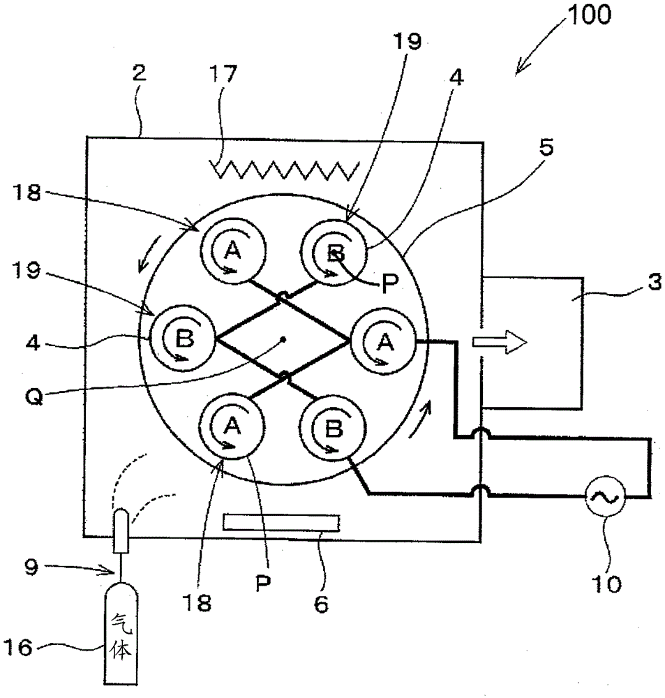
[0034] figure 1 The overall structure of a plasma CVD apparatus 100 as an example of the vacuum film forming apparatus of the present invention is shown. figure 2 This is an example of power connection of the plasma CVD apparatus 100 .

[0035] This plasma CVD apparatus 100 has a vacuum chamber 2 , a vacuum evacuation unit 3 , and a plurality of rotation holding units 4 . The evacuation unit 3 evacuates the inside of the vacuum chamber 2 . Each rotation holding unit 4 holds the substrate W to be film-formed. In addition, each rotation holder 4 rotates while holding the base material W. As shown in FIG. These plurality of rotation holders 4 are provided on the revolution table 5 so that the rotation axes of the respective rotation holders 4 are parallel to each other. This plasma CVD apparatus 100 includes a revolution mechanism 8 . This revolution mechanism 8 revolves the revolution table 5 provided with the plurality of rotation holding parts...

no. 2 approach

[0093] [the whole frame]

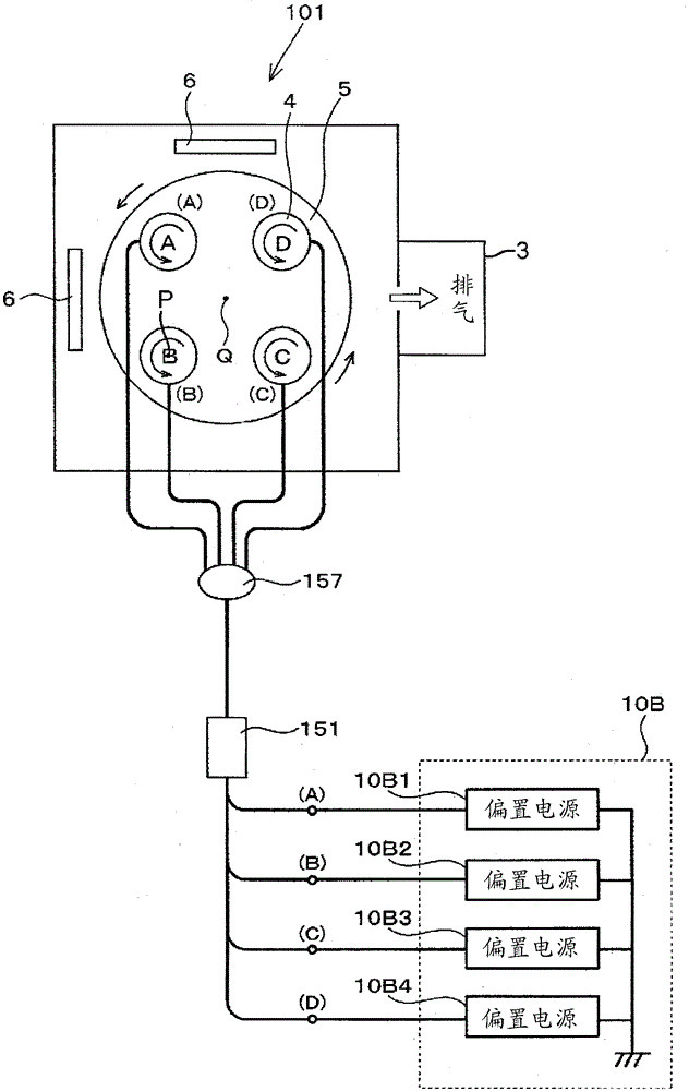
[0094] As follows, while referring to Image 6 An AIP (Arcion Plating) apparatus as an example of the vacuum film forming apparatus of the present invention will be described. Also, since using image 3 (a) ~ Figure 4 The description given is the same as that of the first embodiment, so it will not be repeated here. In addition, the overall structure of the AIP device 101 is the same as that of the figure 1 same.

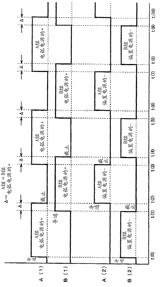
[0095] The AIP device 101 is equipped with an evaporation source 6 (herein an arc evaporation source: refer to Figure 7 ) and a power supply unit 10A having a plurality of outputs capable of supplying (applying) bias voltages to the respective rotation holding portions 4 so that the respective rotation holding portions 4 have potentials different from each other. This AIP apparatus 101 forms a film on the base material W held in each rotation holding part 4 in the same manner as in the first embodiment using the AIP method.

[009...

no. 3 approach

[0126] Hereinafter, the AIP apparatus 102 which is an example of the vacuum film-forming apparatus of this invention is demonstrated. Also, since using image 3 (a) ~ Figure 4 The description is the same as that of the first embodiment, so it will not be repeated here. In addition, the overall structure of the AIP device 102 is the same as that of the figure 1 same.


PUM

PropertyMeasurementUnit
power densityaaaaaaaaaa

Abstract

The vacuum film forming apparatus of the present invention is a vacuum film forming apparatus for forming a film on a base material, and includes: a vacuum chamber; a vacuum exhaust unit for evacuating the inside of the vacuum chamber; a plurality of rotation holding parts of the base material; and a revolving mechanism for revolving the plurality of rotation holding parts around a revolution axis parallel to the rotation axis of each rotation holding part, and the plurality of rotation holding parts are divided into There are a plurality of groups, and electric power is supplied to each rotation holding unit so as to have a different potential for each group. For example, each group repeats time-wise alternately a state in which the negative electrode operates as a working electrode that plays a major role in glow discharge plasma generation, and a state in which it operates as an opposite electrode.

Description

technical field [0001] The present invention relates to a vacuum film-forming method (for example, including ionplating (including AIP method), sputtering method, plasma CVD method and their combination) vacuum film forming device. Background technique [0002] Since the 1980s, in order to improve the life of cutting tools, hard coatings such as TiN and TiAlN have been formed on substrates by vacuum film-forming methods such as AIP (Arc Ion Plating) or sputtering. In addition, in recent years, for the purpose of improving the wear resistance and burn resistance of the surface, CrN and DLC (Diamond-Like-Carbon: Wear-resistant coating (coating) such as diamond-like carbon). [0003] The equipment for performing such vacuum film formation aims to uniformly process a large number of substrates (members) at one time. The film is formed with the voltage for the purpose of plasma generation or film quality adjustment. [0004] For example, Patent Document 1 discloses a film for...

Claims


Application Information

Patent Timeline
Patent Type & Authority Patents(China)
IPC IPC(8): C23C16/458C23C16/509C23C16/515
CPCC23C16/509C23C14/32C23C14/505C23C16/4588H01J37/32036H01J37/32706H01L21/6719H01L21/68764H01L21/68771H01J37/32715C23C16/458C23C16/515C23C14/3464
Inventor 玉垣浩芳贺润二
Owner KOBE STEEL LTD
Why Eureka
Try Eureka