Automatic crimping device for stainless steel pot

A stainless steel pot and crimping device technology, which is applied in the field of auxiliary automation devices, can solve the problems of low flexibility level of the production line, reduced production efficiency, and high maintenance requirements in the later stage.

Active Publication Date: 2015-12-30
XINXING XIANFENG STAINLESS STEEL PROD MFGR CO LTD
View PDF6 Cites 1 Cited by
  • Summary
  • Abstract
  • Description
  • Claims
  • Application Information

AI Technical Summary

Problems solved by technology

The main disadvantages are: the high dependence on manual operation greatly increases the labor intensity of the operators; in addition, due to the fast processing speed of the curling process, the frequency of picking and placing the processed workpieces is high, and repeated single operations are easy to cause fatigue of the operators , thereby slowing down the pace of production and reducing production efficiency
The main disadvantages are: the production line has a low level of flexibility, and it is difficult to realize mixed-line production (multiple products are produced on one production line at the same time), which is not suitable for small and medium batch production; the equipment investment scale is large, and ordinary enterprises cannot bear it; many advanced equipment are used, such as servo systems Etc., high requirements for post-maintenance

Method used


Image

  • Automatic crimping device for stainless steel pot
  • Automatic crimping device for stainless steel pot
  • Automatic crimping device for stainless steel pot

Examples


Embodiment

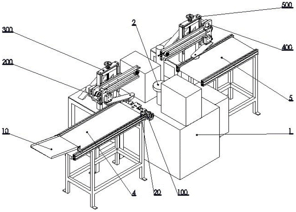
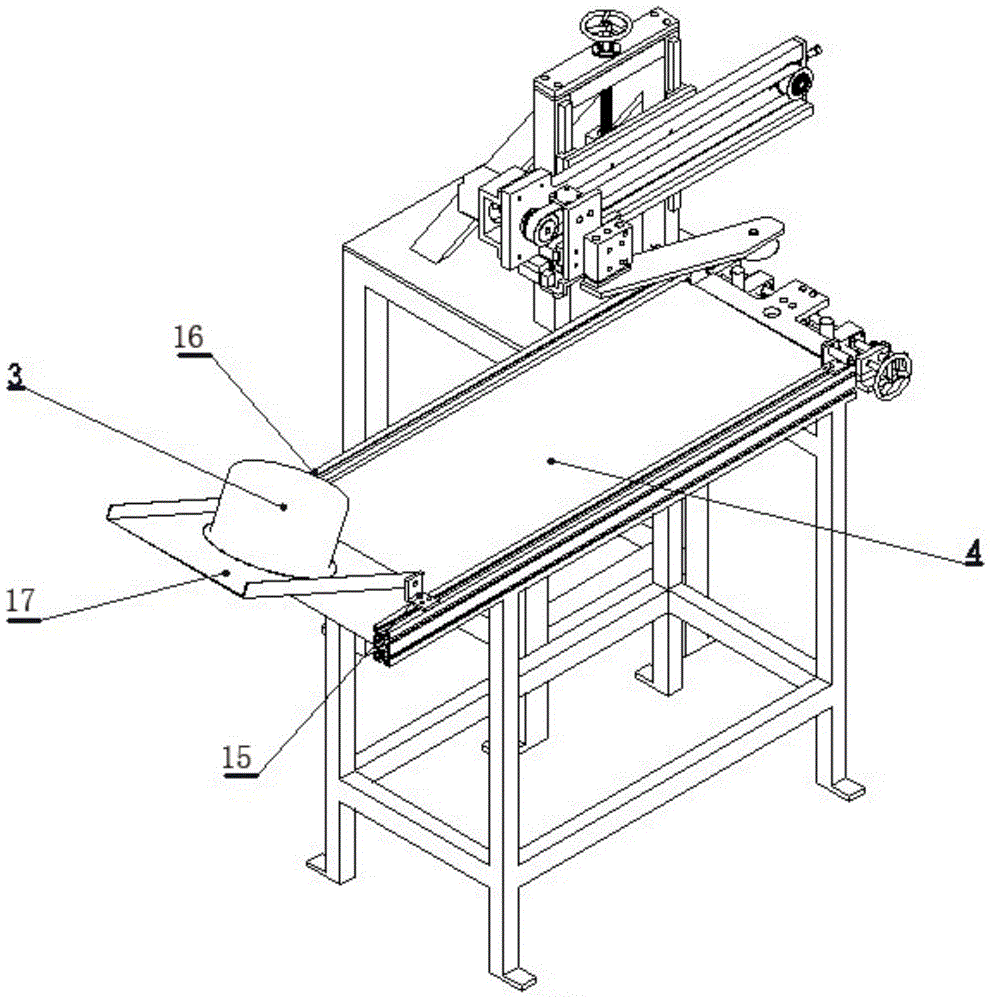
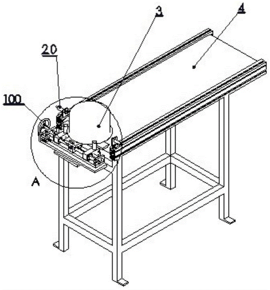
[0058] In this embodiment, the direction from the crimping and discharging mechanism 10 to the retrieving and conveying mechanism 5 is the front-rear direction, the crimping and discharging mechanism 10 is the front, the retrieving and conveying mechanism 5 is the rear, and the direction perpendicular to the front-rear direction is the left-right direction The stainless steel pot enters the crimping discharge mechanism 10 from the previous process and is called the workpiece 3 to be processed, and is called the crimping completion workpiece 6 after the crimping mold 2 operations, and thus unfolds the description.

[0059] refer to figure 1 , an automatic crimping device for a stainless steel pot, comprising a crimping machine 1 and a crimping mold 2 arranged on the crimping machine 1, and also includes:

[0060] Crimping discharge mechanism 10, the crimping discharge mechanism 10 is connected with the equipment of the previous process, and is used to transfer the stainless ste...


PUM


Abstract

The invention discloses an automatic curling device for a stainless steel pot. The automatic curling device comprises a curling machine, a curling mold, a curling discharging mechanism, a feeding conveying mechanism, a positioning detecting mechanism, a feeding mechanical hand mechanism, a feeding mechanical hand lifting fixing mechanism, a material taking mechanical hand mechanism, a material taking mechanical hand lifting fixing mechanism and a material taking conveying mechanism, wherein the feeding conveying mechanism is connected with the curling machine through a positioning device, the positioning detecting mechanism is used for detecting whether the stainless steel pot is located at the designated position of the positioning device or not, the feeding mechanical hand mechanism is located above the feeding conveying mechanism and used for conveying the stainless steel pot from the designated position to the curling mold, the feeding mechanical hand lifting fixing mechanism is used for adjusting the height of the feeding mechanical hand mechanism, the material taking mechanical hand mechanism is used for taking the curled stainless steel pot out of the curling mold, the material taking mechanical hand lifting fixing mechanism is used for adjusting the height of the material taking mechanical hand mechanism, and the material taking conveying mechanism is used for conveying the curled stainless steel pot to the next working procedure. According to the automatic curling device, the contact ratio of sawtooth disc structures is adjusted through a linkage mechanism so as to control the recycling amount of fume, the application range of fuel is wide, and combustion is high in efficiency, stable and low in pollution.

Description

technical field [0001] The invention relates to an automatic crimping device, in particular to an auxiliary automation device invented based on a crimping machine. Background technique [0002] The crimping process is an important process after metal utensils are formed. Taking the stainless steel tableware and kitchenware manufacturing industry as an example, crimping is one of the main production processes in the production process of stainless steel tableware and kitchenware. At present, more than 80% of the domestic stainless steel tableware crimping process is still done manually. The specific process of the crimping operation is: the worker takes the pot—the worker puts the pot into the crimping mold—the crimping machine works—the worker puts the processing The finished workpiece is taken out. [0003] The main advantages of the current stainless steel tableware crimping process are: strong flexibility, fast processing speed, relatively simple process, and low depende...

Claims


Application Information

Patent Timeline
Patent Type & Authority Patents(China)
IPC IPC(8): B21D19/12
Inventor 叶灿雄梁卫民顾世石梁建秀余敬源陈丕立王勇杰陈育贵
Owner XINXING XIANFENG STAINLESS STEEL PROD MFGR CO LTD
Why Eureka
Try Eureka