Oscillating-arc narrow-gap MIG/MAG (Metal Inert Gas/Metal Active Gas) welding torch

A narrow gap and welding torch technology, which is applied in arc welding equipment, electrode accessories, welding rod characteristics, etc., can solve the problems of unfused side walls, etc., to solve the problems of unfused side walls, large welding plate thickness, and high welding production efficiency Effect

Active Publication Date: 2014-03-26
HARBIN INST OF TECH
View PDF6 Cites 10 Cited by
  • Summary
  • Abstract
  • Description
  • Claims
  • Application Information

AI Technical Summary

Problems solved by technology

[0003] The present invention provides a swing arc narrow gap MIG / MAG welding torch in order to solve the problem of unfused side walls in narrow gap welding

Method used


Image

  • Oscillating-arc narrow-gap MIG/MAG (Metal Inert Gas/Metal Active Gas) welding torch
  • Oscillating-arc narrow-gap MIG/MAG (Metal Inert Gas/Metal Active Gas) welding torch
  • Oscillating-arc narrow-gap MIG/MAG (Metal Inert Gas/Metal Active Gas) welding torch

Examples


specific Embodiment approach 1

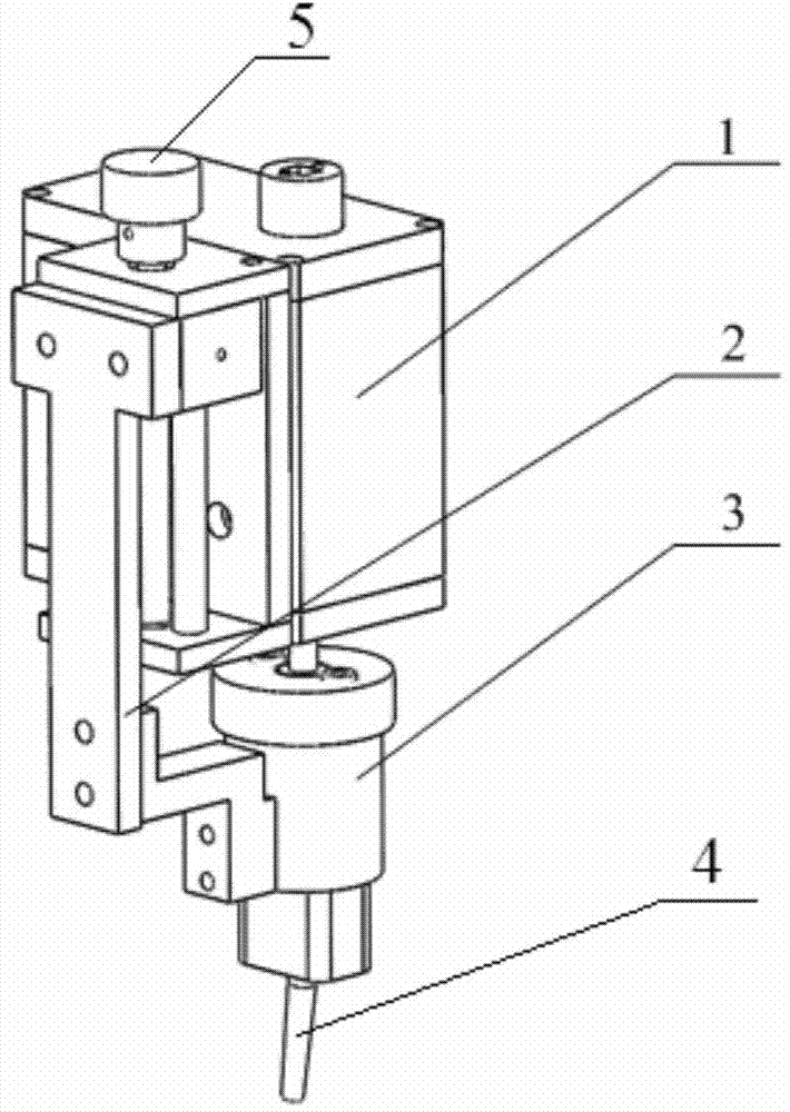
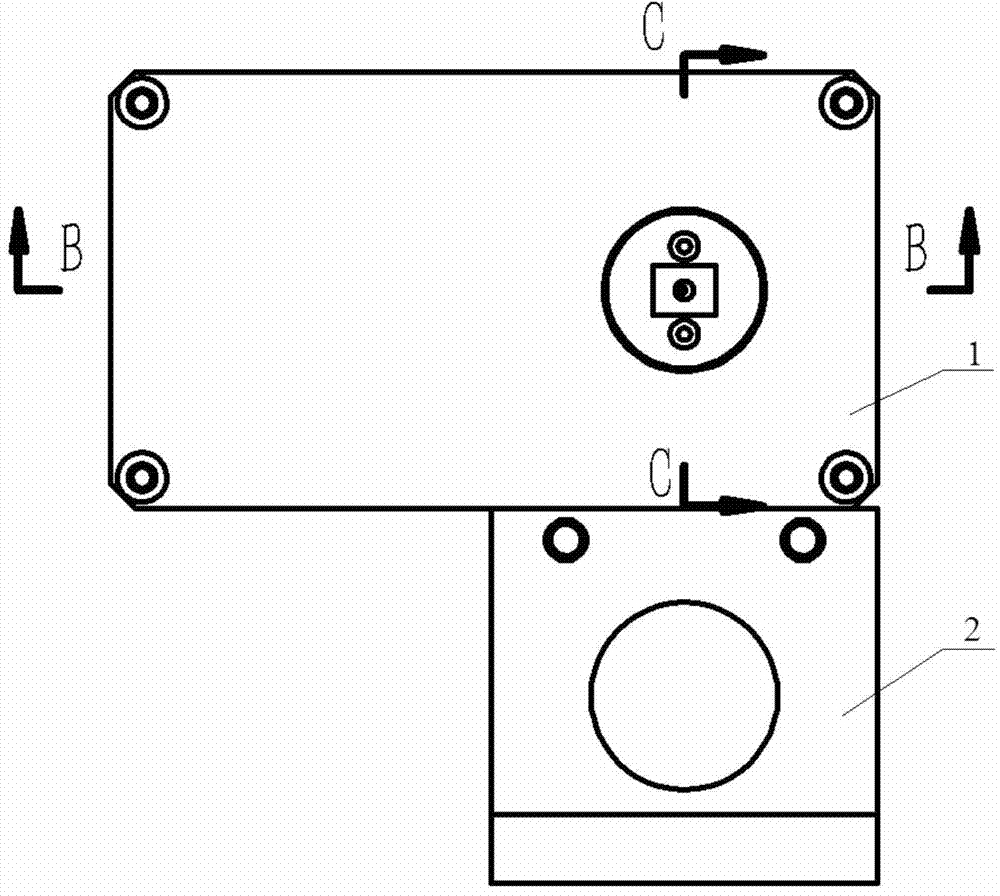
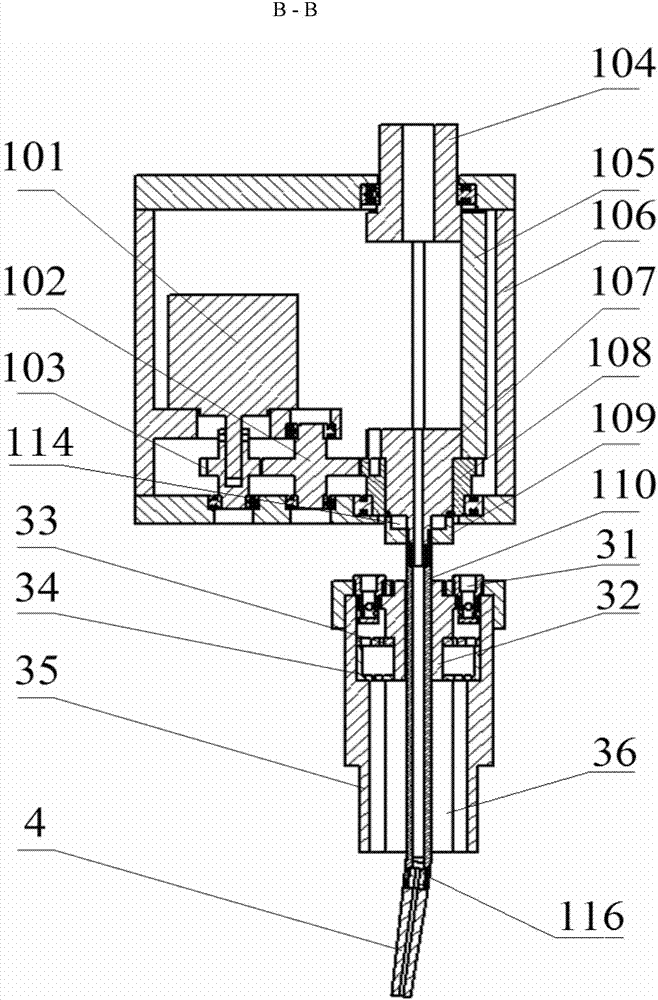
[0012] Specific implementation mode one: combine Figure 1 ~ Figure 4 Describe this embodiment. This embodiment includes a welding torch main body 1, a nozzle height adjustment part 2, an external narrow gap nozzle 3 and a conductive tip 4. The welding torch main body 1 includes a welding torch housing 106, a swing mechanism and a conductive cooling device. The swing mechanism includes a motor 101, motor gear 103, transition gear 102 and swing gear 108, motor gear 103 is fixed on the output shaft of motor 101, transition gear 102 meshes with motor gear 103 and swing gear 108 at the same time, conductive cooling device includes welding torch joint 104, conductive plate 105, conductive shaft 107, conductive shaft sleeve 109, curved conductive rod 110 and two water pipes 112, the two ends of the conductive plate 105 are respectively connected with the welding torch joint 104 and the conductive shaft 107, the conductive shaft 107 is arranged in the center hole of the swing gear 108...

specific Embodiment approach 2

[0014] Specific implementation mode two: combination image 3 Describe this embodiment, the external narrow gap nozzle 3 of this embodiment comprises a nozzle housing 35, a filter screen 33, a secondary filter screen 34 and a central bushing 32, the central bushing 32 is placed in the center of the nozzle, and the central bushing 32 and the Two air inlets 31 are arranged between the nozzle housings 35 , the air inlets 31 communicate with the lower cavity 36 of the nozzle housing 35 , and the primary filter 33 and the secondary filter 34 are arranged below the two air inlets 31 up and down. The protective gas enters the interior of the nozzle 3 through the two air inlets 31 on the upper end of the nozzle shell, is filtered and calmed by the primary filter 33 and the secondary filter 34, and finally exits from the lower end of the nozzle 3. The central bushing 32 is placed in the center of the nozzle and is curved and conductive Rod 110 passes through central hub 32 . Other com...

specific Embodiment approach 3

[0015] Specific implementation mode three: combination image 3 To describe this embodiment, the axis of the bending head 116 and the axis of the conductive shaft 107 in this embodiment form an included angle of 6°. Other components and connections are the same as those in the first embodiment.


PUM


Abstract

The invention relates to an oscillating-arc narrow-gap MIG / MAG (Metal Inert Gas / Metal Active Gas) welding torch to solve the problem that side walls are not fused during narrow-gap welding. A motor gear is fixedly arranged on an output shaft of a motor. A transition gear is synchronously engaged with the motor gear and an oscillating gear. Two ends of a conductive plate are respectively connected with a welding gun connector and a conductive shaft. The conductive shaft is arranged in a center hole of the oscillating gear and is fixedly connected with the oscillating gear. A conductive shaft sleeve and the conductive shaft form a cavity. The cavity is communicated with two water holes formed in the conductive shaft. Two water pipes respectively communicate a water inlet and a water outlet with the two water holes in the conductive shaft. The upper end of a bent conductive rod is connected onto the conductive shaft through a thread and the lower end of the bent conductive rod penetrates through an external narrow-gap spray nozzle. The axis of a bending head at the lower part of the bent conductive rod and the axis of the conductive shaft form an included angle of 5-15 degrees. A contact tip is connected onto the bending head through a thread. A spray nozzle height adjusting part is installed on the shell of the welding gun. The external narrow-gap spray nozzle is fixedly arranged below the spray height adjusting part. The oscillating-arc narrow-gap MIG / MAG welding torch is used for narrow-gap welding.

Description

technical field [0001] The invention relates to a narrow gap welding technology, in particular to a swing arc narrow gap MIG / MAG welding torch. Background technique [0002] Narrow gap welding is an efficient welding technique. On the basis of traditional arc welding, it changes the groove form to I-shaped grooves or U-shaped grooves with small angles between 0.5° and 7°. Narrow gap welding technology has many advantages when welding thick plates. Due to the use of small-sized grooves in narrow-gap welding, compared with traditional welding methods, the cross-sectional area of ​​the weld is greatly reduced, which can save a lot of welding materials and significantly improve production efficiency; at the same time, it can reduce welding heat input, reduce welding deformation and Welding residual stress is conducive to the improvement of welding quality. In the traditional welding field, the GMAW method is one of the most widely used welding methods, and it has many charact...

Claims


Application Information

Patent Timeline
Patent Type & Authority Applications(China)
IPC IPC(8): B23K9/26B23K9/28B23K9/16B23K9/32
CPCB23K9/173B23K9/26B23K9/28B23K9/285
Inventor 林三宝徐望辉范成磊杨春利
Owner HARBIN INST OF TECH
Why Eureka
Try Eureka