

Friction stir welding apparatus
A friction stirring and joining device technology, which is applied in welding equipment, welding/welding/cutting items, non-electric welding equipment, etc., can solve the problems of complicated structure and no enlightenment, and achieve the effect of simple structure
- Summary
- Abstract
- Description
- Claims
- Application Information
AI Technical Summary
Problems solved by technology
Method used
Image

Examples
no. 1 Embodiment approach )
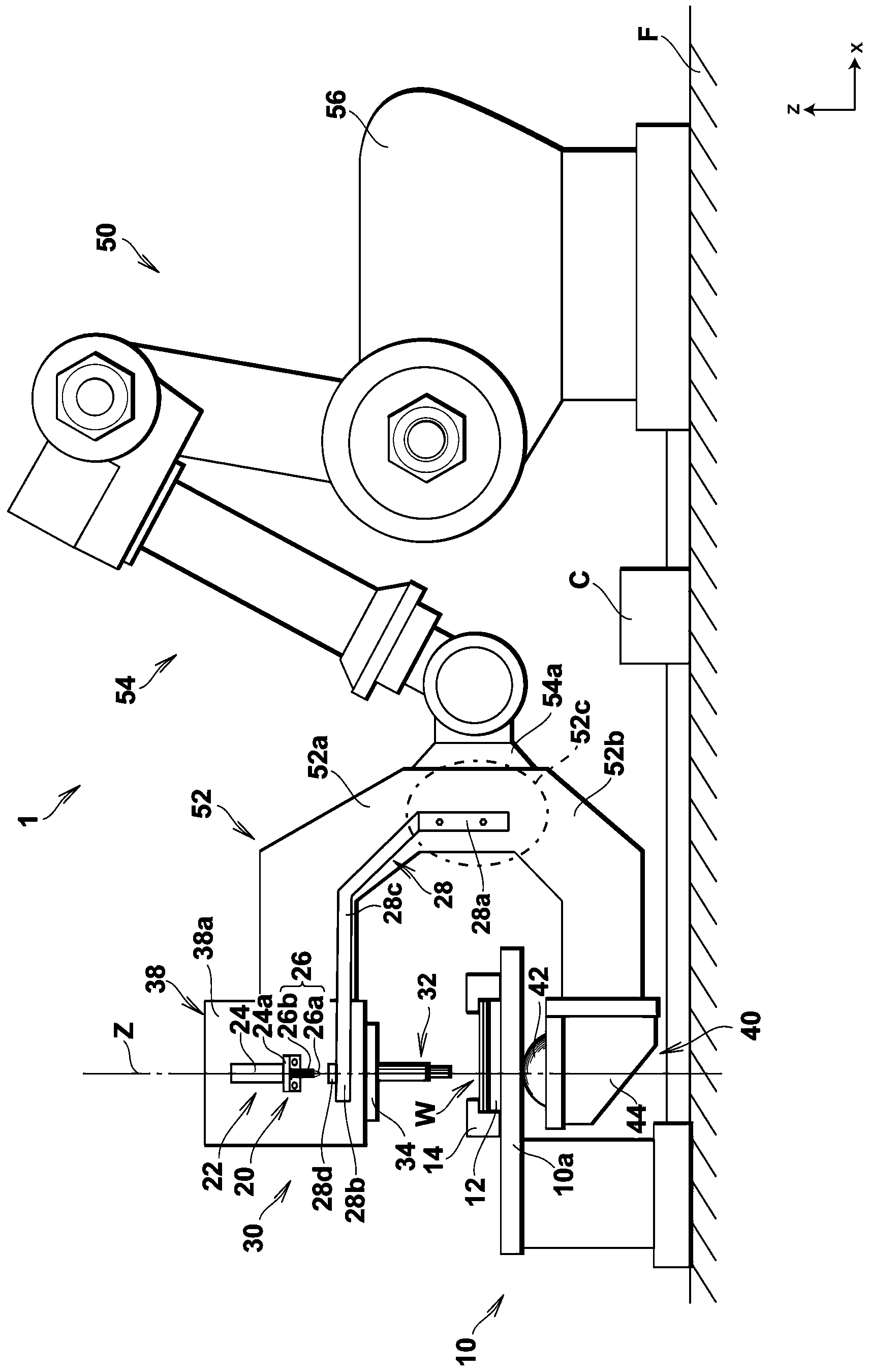
[0101] First, refer to figure 1 Moving to FIG. 7 , the friction stir welding device according to the first embodiment of the present invention will be described in detail.
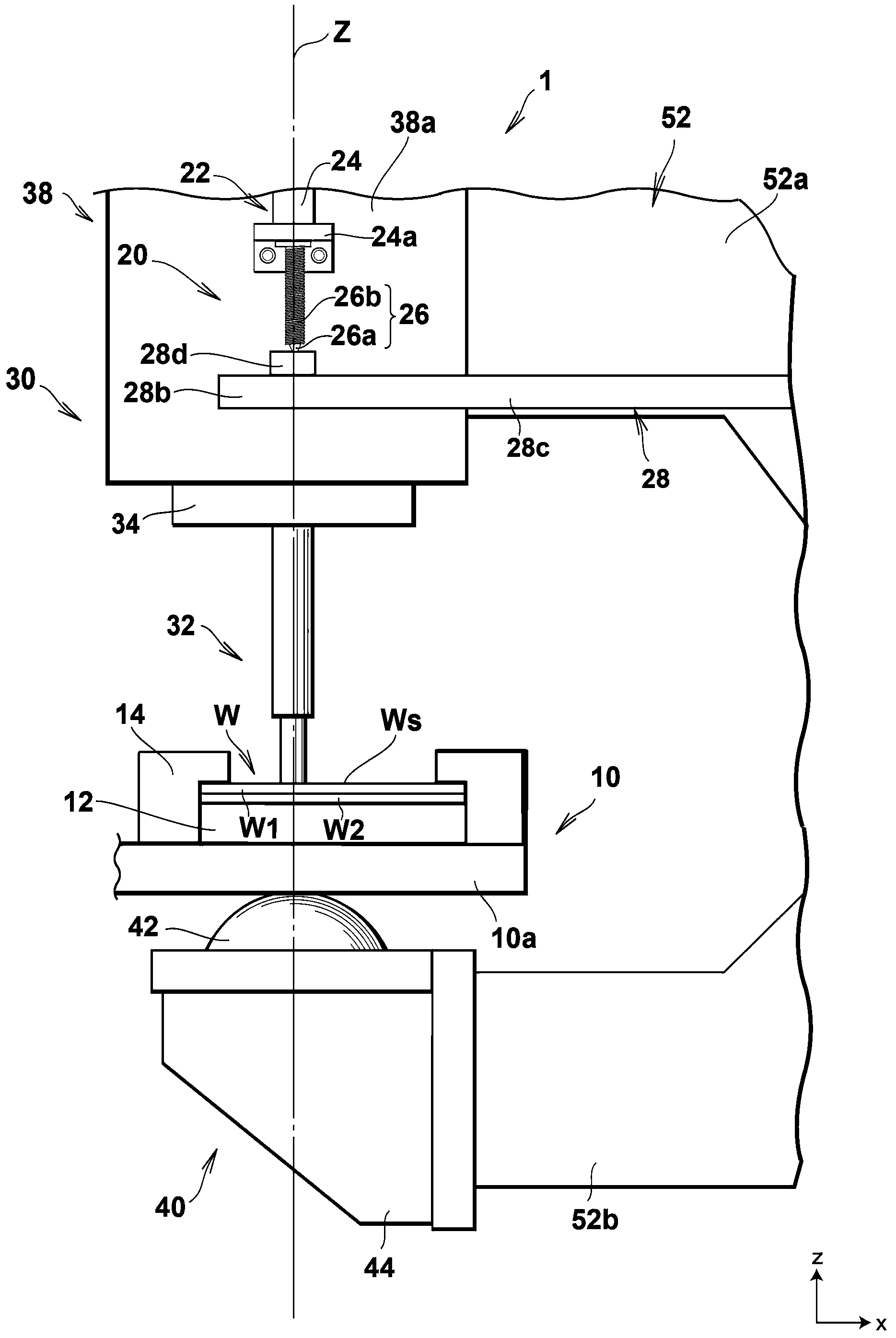
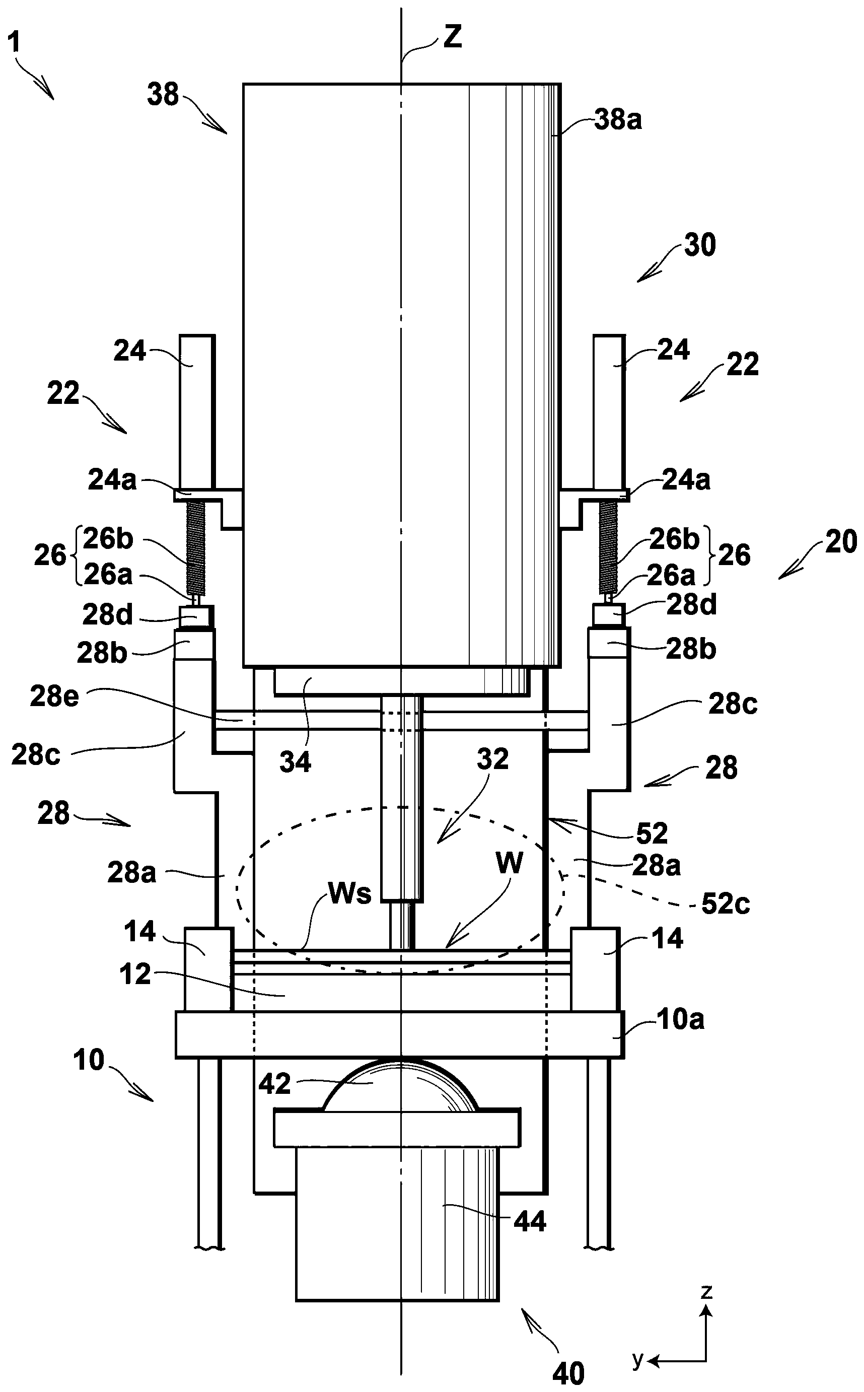
[0102] figure 1 It is a side view showing the overall structure of the friction stir welding device of this embodiment. figure 2 It is a partial enlarged side view of the friction stir welding apparatus of this embodiment. also, image 3 It is a partial enlarged front view of the friction stir welding apparatus of this embodiment.
[0103] Such as Figure 1 to Figure 3 As shown, the friction stir welding apparatus 1 includes: a mounting table 10 fixedly installed on a floor F for mounting a workpiece W to be processed; a displacement detection device 20 facing the mounting table 10 above the mounting table 10 The joint tool 30 is equipped with a displacement detection device 20, and the joint tool 30 is freely disposed above the mounting table 10 in a manner opposite to the mounting table 10; the aux...
no. 2 Embodiment approach )
[0164] Next, further reference Figure 8 to Figure 1 2. The friction stir welding apparatus according to the second embodiment of the present invention will be described in detail.
[0165] Figure 8 It is a side view showing the overall structure of the friction stir welding device of this embodiment. Figure 9A It is a partial enlarged side view of the friction stir welding device of this embodiment, Figure 9B for Figure 9A A cross-sectional view along line A'-A'. Figure 10A is only shown Figure 8 Enlarged view of the mounting fixture, drive mechanism and auxiliary support mechanism, Figure 10B is viewed along the negative direction of the z-axis Figure 10A top view of , in addition, Figure 10C is viewed along the positive direction of the z-axis Figure 10A bottom view. Figure 11A is viewed along the positive direction of the x-axis Figure 10A main view of Figure 11B For viewing along the negative direction of the x-axis Figure 10A rear view. Figure...
PUM
 Abstract
Description
Claims
Application Information