
Fully automatic continuous annealing system for amorphous strip

An amorphous strip material and fully automatic technology, applied in the field of fully automatic systems, can solve the problems of manpower consumption, poor consistency, and low work efficiency, and achieve the effects of reducing the number of times of overshooting temperature, achieving poor consistency, and ensuring reliability

Active Publication Date: 2015-10-21
QINGDAO YUNLU ADVANCED MATERIALS TECH CO LTD
View PDF7 Cites 0 Cited by
  • Summary
  • Abstract
  • Description
  • Claims
  • Application Information

AI Technical Summary

Problems solved by technology

[0003] The traditional annealing process is to manually send the strip into the annealing furnace, manually control the temperature in the annealing furnace, and manually collect the annealed strip. The work of collecting and collecting not only consumes manpower and is inefficient, but more importantly, the manual operation method is unstable and poor in consistency, especially when touching the strip with bare hands, it will affect the performance of the strip and directly affect the reliability of the strip detection results. Reliability; 2. Manual temperature control needs to monitor the temperature in the annealing furnace all the time. Due to the hysteresis of temperature transmission, it is difficult to achieve a stable rise to a certain temperature within the specified temperature time during the annealing process, resulting in unstable temperature control. The consistency is poor, which directly affects the credibility of the test results; 3. Due to the manual work of feeding and collecting, the work efficiency is low, resulting in poor air tightness in the annealing furnace and the inability to maintain a high degree of oxygen-free environment, resulting in Oxidation of the material affects the quality and performance of the amorphous strip

Method used


Image

  • Fully automatic continuous annealing system for amorphous strip
  • Fully automatic continuous annealing system for amorphous strip
  • Fully automatic continuous annealing system for amorphous strip

Examples


Embodiment Construction

[0038] The present invention will be described in detail below in conjunction with the accompanying drawings.

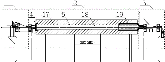
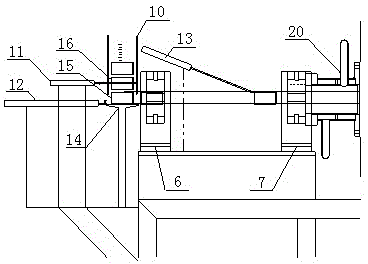
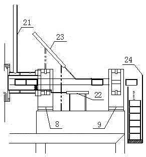
[0039] The technical solution of this embodiment is: a fully automatic amorphous strip continuous annealing system, mainly composed of a feeding part 1, a heat treatment part 2, a feeding part 3 and a control part, the feeding part 1 and the feeding part 3 are respectively Located on the left and right sides of the heat treatment part 2; the heat treatment part 2 includes an annealing furnace 4; a metal rod 5 is arranged in the annealing furnace 4 and extends transversely through the furnace, and four valves for fixing the metal rod 5 are arranged outside the annealing furnace 4 ; The feeding part 1 is used to cover the amorphous strip on the metal rod 5 and is sent into the annealing furnace 4, the heat treatment part 2 is used to heat the amorphous strip, add a magnetic field and cool it, and the retrieving part 3 is used After the amorphous strip is taken out from...


PUM


Abstract

The invention relates to a full automatic continuous annealing system for an amorphous strip, which mainly comprises a material loading part, a heat treatment part, a material taking part and a control part, wherein the material loading part and the material taking part are respectively positioned on the left side and the right side of the heat treatment part; the heat treatment part comprises an annealing furnace; a metal rod is arranged in the annealing furnace, and transversely penetrates through and extends out of the annealing furnace, and four or more valves for fixing the metal rod are arranged outside the annealing furnace; the material loading part is used for enabling the amorphous strip to be sleeved upon the metal rod and conveying the amorphous strip to the annealing furnace, the heat treatment part is used for performing the heating, magnetic field increment and cooling on the amorphous strip, the material taking part is used for taking out the amorphous strip from the annealing furnace and separating the amorphous strip from the metal rod, and the control part is used for controlling the operations of all the parts. The full automatic continuous annealing system for the amorphous strip can achieve full automatic material feeding, material taking and non-overshooting automatic temperature control, and has the characteristics of low manufacturing cost, simple structure, high precision and stable performance.

Description

technical field [0001] The invention relates to a fully automatic system for continuous annealing of annular amorphous strips. Background technique [0002] In the production and testing process of amorphous strip, it is often necessary to anneal the annular amorphous strip. For example, in the process of manufacturing annular amorphous inductor core, the performance of the annular amorphous strip It needs to be annealed before it is heated, cooled and applied with a magnetic field. [0003] The traditional annealing process is to manually send the strip into the annealing furnace, manually control the temperature in the annealing furnace, and manually collect the annealed strip. The work of collecting and collecting not only consumes manpower and is inefficient, but more importantly, the manual operation method is unstable and poor in consistency, especially when touching the strip with bare hands, it will affect the performance of the strip and directly affect the reliabi...

Claims


Application Information

Patent Timeline
Patent Type & Authority Patents(China)
IPC IPC(8): C21D9/56C21D11/00
Inventor 康博强王安庆
Owner QINGDAO YUNLU ADVANCED MATERIALS TECH CO LTD
Learn More