
A continuous heat treatment device and mgb 2 Superconducting wire/strip heat treatment method

A heat treatment method and superconducting wire technology, applied in the field of heat treatment, can solve problems such as long heating and cooling time, wire/strip adhesion, affecting the superconductivity of wire/strip, and achieve the effects of improving heat treatment, improving quality, and increasing length

Active Publication Date: 2020-06-26
NORTHWEST INSTITUTE FOR NON-FERROUS METAL RESEARCH
View PDF4 Cites 0 Cited by
  • Summary
  • Abstract
  • Description
  • Claims
  • Application Information

AI Technical Summary

Problems solved by technology

[0004] Traditional MgB 2 The wire / strip heat treatment method is static heat treatment, that is, MgB 2 The wire / strip is rolled into a disc and heat-treated at a constant temperature. If the wire / strip is long, it needs to be placed in a large-scale heat treatment equipment, but the heating and cooling time of a large-scale heat treatment equipment is long, which may easily lead to MgB 2 MgB of wire / strip 2 The transformation of the superconducting core wire or the diffusion reaction with the cladding material will generate a non-superconducting impurity phase, and the long-term high temperature will make the MgB 2 Sticking between wires / strips, eventually affecting MgB 2 Superconducting properties of wire / strip

Method used


Image

  • A continuous heat treatment device and mgb  <sub>2</sub> Superconducting wire/strip heat treatment method

Examples


Embodiment 1

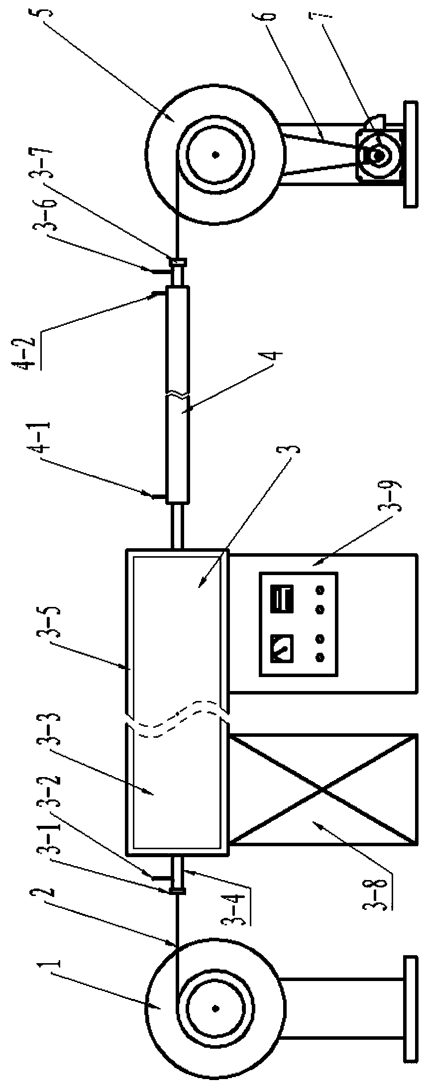
[0032] Such as figure 1The shown continuous heat treatment device includes a heat treatment furnace 3, and the heat treatment furnace 3 includes a furnace body 3-3, a temperature controller 3-9 and a furnace frame 3-8 for supporting the furnace body 3-3. The furnace body 3-3 is pierced with a furnace tube 3-4, and both ends of the furnace tube 3-4 extend out of the furnace body 3-3, and the two ends of the furnace tube 3-4 are respectively equipped with a furnace tube inlet end The cap mouth 3-1 and the furnace pipe outlet end cap mouth 3-7, the furnace pipe 3-4 is equipped with an air inlet 3-2 at one end of the furnace pipe inlet cap mouth 3-1, and the furnace pipe 3-4 An air outlet 3-6 is provided at one end of the cap opening 3-7 of the outlet end of the furnace tube, and a sleeve cooler 4 is set on the furnace tube 3-4 close to the cap opening 3-7 of the outlet end of the furnace tube. The tube cooler 4 is provided with a cooling water inlet 4-1 and a cooling water outle...

Embodiment 2

[0036] This embodiment includes the following steps:

[0037] Step 1. Put the 12-core MgB 2 The starting end of the superconducting strip is connected with one end of the lead wire 2 passing through the cap opening 3-1 of the inlet end of the furnace tube, and then wound on the pay-off wheel 1, and then the other end of the lead wire 2 is passed through the cap opening 3 of the outlet end of the furnace tube -7 is wound on the take-up reel 5; the 12-core MgB 2 The cross-section of the superconducting tape is a rectangle of 0.4mm×3.2mm;

[0038] Step 2. Adjust the temperature in the furnace tube 3-4 to 650°C through the temperature controller 3-9, pass the argon gas into the furnace tube 3-4 through the air inlet 3-2, and push the air from the air outlet 3-6 Discharge, then close the air inlet 3-2 and the exhaust hole 3-6, make the furnace tube 3-4 stable at 650°C for 10 minutes, and then pass the water into the sleeve cooler 4 through the cooling water inlet 4-1 , discharge...

Embodiment 3

[0047] This embodiment includes the following steps:

[0048] Step 1, the 7-core MgB 2 The starting end of the superconducting wire is connected to one end of the lead wire 2 passing through the cap opening 3-1 of the inlet end of the furnace tube, and then wound on the pay-off wheel 1, and then the other end of the lead wire 2 is passed through the cap opening 3-1 of the outlet end of the furnace tube. 7 is wound on the take-up reel 5; The 7-core MgB 2 The diameter of the superconducting wire is 1.0mm;

[0049] Step 2. Adjust the temperature in the furnace tube 3-4 to 700°C through the temperature controller 3-9, pass the argon gas into the furnace tube 3-4 through the air inlet 3-2, and push the air from the air outlet 3-6 Discharge, then close the air inlet 3-2 and the exhaust hole 3-6, make the furnace tube 3-4 stable at 700°C for 10 minutes, and then pass the water into the sleeve cooler 4 through the cooling water inlet 4-1 , discharged from the cooling water outlet 4...


PUM

PropertyMeasurementUnit
diameteraaaaaaaaaa
diameteraaaaaaaaaa

Abstract

The invention discloses a continuous heat treatment device, which uses a motor to drive the take-up wheel to rotate through a transmission belt, so as to drive the lead wire to pull the material to be heat treated to pass through the heating zone and cooling zone of the heat treatment device in sequence, and perform dynamic continuous heat treatment and cooling treatment. One step realizes the rapid temperature rise and fall of the material, reduces the temperature difference at different positions of the material during the heat treatment process, improves the quality of the heat treatment, and expands the application range of the device. The invention also discloses a MgB 2 Method for heat treatment of superconducting wire / strip, the method will MgB 2 The superconducting wire / strip is placed in the above-mentioned continuous heat treatment device, and then the heat treatment of continuous rapid temperature rise and fall is carried out under the protection of an inert gas, which avoids the MgB 2 The superconducting core wire generates non-superconducting impurity phases and MgB 2 The phenomenon of sticking between wires / strips is flexible and controllable, convenient and efficient.

Description

technical field [0001] The invention belongs to the technical field of heat treatment, in particular to a continuous heat treatment device and MgB 2 Superconducting wire / strip heat treatment method. Background technique [0002] Heat treatment is a thermal processing process that changes the chemical composition and organization of the surface or interior of a material through temperature to obtain the desired properties. The conventional heat treatment method is static heat treatment, that is, the material to be heat treated is loaded into a heat treatment device, and the heat treatment process is realized by controlling the temperature and time of heat treatment. The larger the amount of heat treatment, the larger the specification of the heat treatment device is required, but the heating and cooling time of the large heat treatment device is longer, the temperature difference between different positions in the material is large during heat treatment, the effect of heat t...

Claims


Application Information

Patent Timeline
Patent Type & Authority Patents(China)
IPC IPC(8): H01B13/00H01L39/24
CPCH01B13/0016H10N60/0856
Inventor 王庆阳闫果潘熙锋杨芳熊晓梅郗丹冯建情李成山张平祥
Owner NORTHWEST INSTITUTE FOR NON-FERROUS METAL RESEARCH
Learn More