Electrolysis high temperature steam hydrogen production device and hydrogen production method

A high-temperature water vapor and hydrogen production device technology, applied in the direction of electrolysis process, electrolysis components, cells, etc., can solve the problems of complex process, high cost, low hydrogen efficiency, etc., and achieve the effect of reducing cost and improving efficiency

Active Publication Date: 2016-01-13
王树金
View PDF4 Cites 0 Cited by
  • Summary
  • Abstract
  • Description
  • Claims
  • Application Information

AI Technical Summary

Problems solved by technology

[0016] The purpose of the present invention is to provide an electrolytic high-temperature steam hydrogen production device, which solves the problems that the current hydrogen production device has low hydrogen production efficiency, complicated process and high cost, and cannot meet the actual needs

Method used


Image

  • Electrolysis high temperature steam hydrogen production device and hydrogen production method

Examples


Embodiment 1

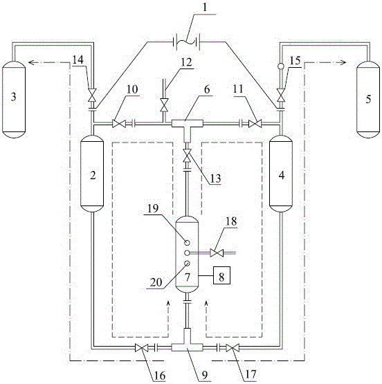
[0033] figure 1 It is a structural schematic diagram of the present invention, as shown in the figure, the electrolysis high-temperature steam hydrogen production device includes a power supply 1, a H depolymerization kettle 2, a H 2 Collector 3, O Depolymerization kettle 4, O 2 Collector 5, heat conduction bridge 6, heat collector 7, heating furnace 8 and electrolytic bridge 9, wherein, power supply 1 connects H depolymerization kettle 2 and O depolymerization kettle 4 through electrodes, H depolymerization kettle 2 and H 2 collector 3 connection, O depolymerization tank 4 and O 2 Collector 5 is connected. The power supply provides current, and the electrolysis of sodium hydroxide aqueous solution produces hydrogen and oxygen, and the hydrogen is replaced by H 2 Collector collects, oxygen is collected by O 2 The collector collects. The role of the electrode is to fully contact with the sodium hydroxide aqueous solution to provide current to ensure sufficient electrolysis...

Embodiment 2

[0041] A method for producing hydrogen using an electrolytic high-temperature steam hydrogen production device, the method comprising the following steps:

[0042] (1) Heating: Start the heating furnace 8 to heat up the heat collector 7, and stop after the pipeline is filled with water vapor; as shown in the figure, the dotted arrow indicates the flow direction of water vapor, and the water vapor rises from the heat collector to After the heat conduction bridge, enter the H depolymerization kettle and the O depolymerization kettle on both sides, and then flow down to the electrolysis bridge. As a result, the pipeline is filled with water vapor. At this time, the heating step can be stopped and the electrolysis step can be entered;

[0043] (2) Electrolysis: close valve one 10, valve two 11, valve three 13, open the pressure relief port 12, and drain the water vapor in the heat conduction bridge, so that the heat conduction bridge forms a blocking insulation, therefore, the cond...


PUM

PropertyMeasurementUnit
heating valueaaaaaaaaaa
specific heat capacityaaaaaaaaaa

Abstract

The present invention relates to an electrolytic high-temperature steam hydrogen production device, which includes a power supply, an H depolymerization kettle, an H2 collector, an O depolymerization kettle, an O2 collector, a heat conduction bridge, a heat collector, a heating furnace and an electrolytic bridge, wherein , the power supply is connected to the H depolymerization kettle and the O depolymerization kettle through the electrodes, the H depolymerization kettle is connected to the H2 collector, and the O depolymerization kettle is connected to the O2 collector; the thermal bridge is located between the H depolymerization kettle and the O depolymerization kettle, And the H depolymerization kettle and the O depolymerization kettle are respectively connected by pipelines; the electrolytic bridge is located at the lower part of the H depolymerization kettle and the O depolymerization kettle, and the H depolymerization kettle and the O depolymerization kettle are respectively connected by pipelines ; The heat collector is located between the heat conduction bridge and the electrolytic bridge, and a heating furnace is installed under the heat collector. The invention is a closed system. After heating the water in the "electrolytic kettle" into high-temperature (pressure) steam in the system, the "electrolytic kettle" is loaded with direct current to prepare hydrogen, which can greatly improve the efficiency of hydrogen production.

Description

technical field [0001] The invention belongs to the field of new energy, and relates to an electrolytic high-temperature steam hydrogen production device and a hydrogen production method. Background technique [0002] At present, with the development and utilization of various energy sources, countries all over the world are looking for and developing hydrogen energy. As a new energy source, hydrogen energy is waiting to replace traditional energy sources. However, so far, all hydrogen production methods in the world. Such as: direct current electrolysis of water to produce hydrogen (that is, the traditional method), solar thermal water decomposition to produce hydrogen, solar power generation to electrolyze water to produce hydrogen, sunlight catalytic photolysis of water to produce hydrogen, solar biological hydrogen production and many other methods, due to high cost and low production efficiency. Substantial breakthroughs are required to reduce or pollute the environmen...

Claims


Application Information

Patent Timeline
Patent Type & Authority Patents(China)
IPC IPC(8): C25B1/12C25B9/00
CPCC25B1/04C25B9/00C25B15/08C25B9/05Y02E60/36
Inventor 王树金薛瑞飞薛瑞艳
Owner 王树金
Why Eureka
Try Eureka