

Road and bridge expansion joint structure
A technology of expansion joints and structures, applied in bridges, bridge parts, bridge construction, etc., can solve the problems of reduced service life of bridges, poor weather resistance of expansion joints, poor anti-aging performance, etc., and achieves extended service life and residual stability The effect of large degree, increased sealing strength and the ability to withstand external forces
Inactive Publication Date: 2014-03-26
孟献春
View PDF7 Cites 14 Cited by
- Summary
- Abstract
- Description
- Claims
- Application Information
AI Technical Summary
Problems solved by technology
The deformation of the bridge deck produces a large stress at the expansion device. If the expansion device does not have a certain strength, it is easy to be damaged. Similarly, if the flatness of the expansion joint is not good, it is easy to be damaged under the action of the vehicle load. Large impact, also easily damaged
Due to the shrinkage and creep of concrete, the deflection caused by various loads, the uneven layer drop of the base, the longitudinal slope of the bridge deck, and the driving force of the vehicle, etc., the expansion joints have early failure, deformation of the joint body, and local spalling of the cast-in-place concrete surface. It is especially common; on the other hand, with the growth of bridge age, due to the effect of natural factors such as environment and climate, the increasing traffic volume and the increasing number of heavy vehicles and overweight vehicles crossing the bridge, as well as human accidents and other factors, also make The probability of damage to expansion joints is too high
Once the expansion joint is damaged, it will not only make the passengers feel uncomfortable and lack a sense of security, but also the impact of the vehicle on the upper structure due to its damage will not only deteriorate the driving condition, but also affect the force of the main structure of the bridge. To reduce the service life of the bridge, it must be repaired or completely replaced at this time, otherwise it will seriously affect the normal traffic, cause economic losses and adverse effects to varying degrees, and even endanger the safety of the bridge. The traditional expansion joint structure has poor weather resistance , can not be heated for a long time, it is easy to age under long-term sunlight, the anti-aging performance is not good, and the service life is obviously shortened; it is easy to produce bubbles and cracks in a high-humidity environment
Method used
View moreImage
Smart ImageViewing Examples

Examples
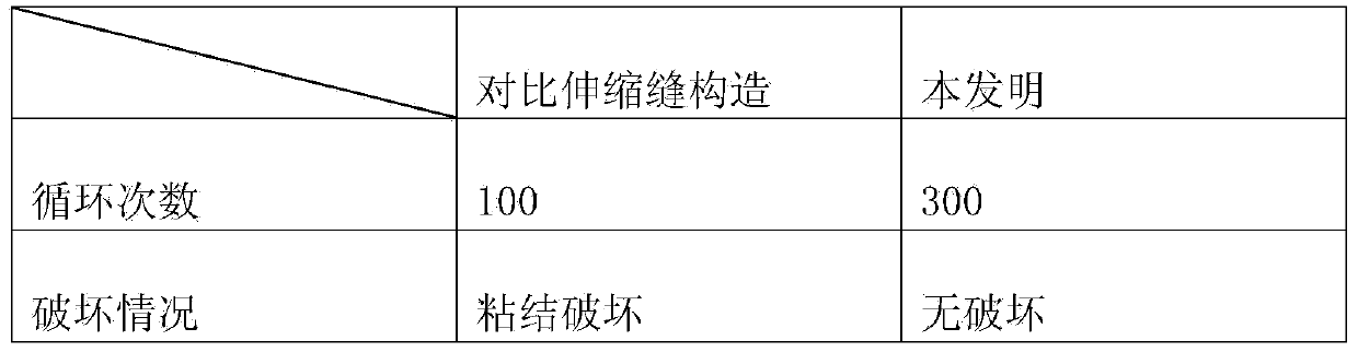
Embodiment 1
Embodiment 2
Embodiment 4
Login to View More PUM
| Property | Measurement | Unit |
|---|---|---|
| thickness | aaaaa | aaaaa |
| elongation | aaaaa | aaaaa |
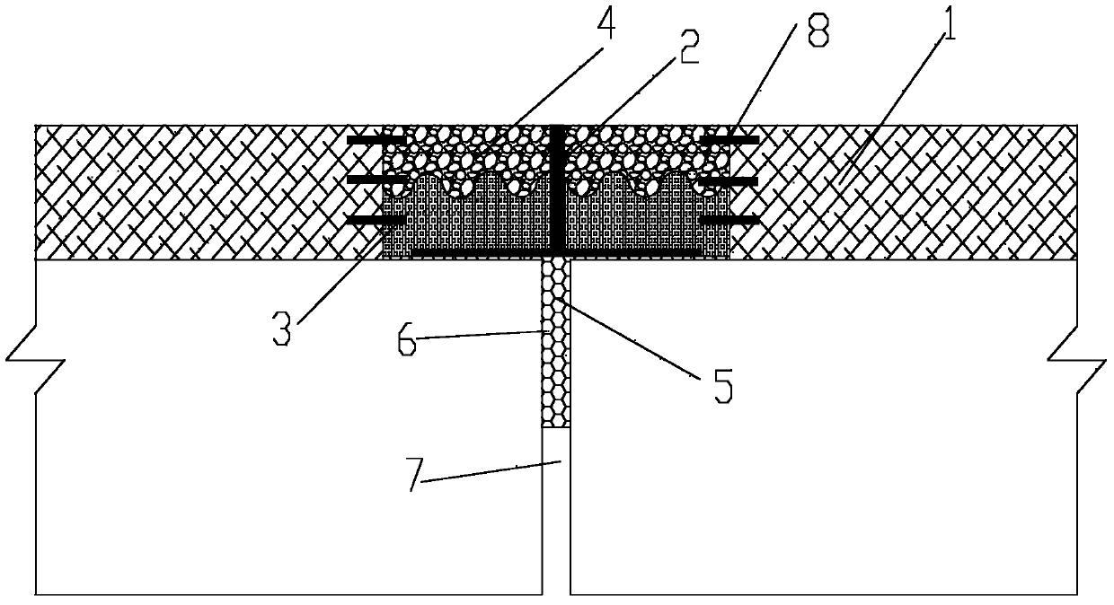
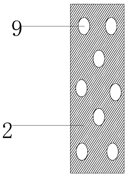
Abstract
The invention discloses a road and bridge expansion joint structure. The road and bridge expansion joint structure comprises an inverted-T-shaped plate component with the bridge longitudinal cross section being in an inverted T shape. Two wing plates of the inverted-T-shaped plate component transversely extend into a base body of a bridge pavement layer. A web extends upwards to be flush with the upper surface of the bridge pavement layer. Each wing plate is sequentially provided with a cushion layer and a protection wear-resisting layer from bottom to top in a laying mode and is longitudinally connected with the bridge pavement layer. An expansion joint notch and the two sides of the expansion joint notch are filled with elastic layers to be sealed. The road and bridge expansion joint structure has the advantages of being convenient to construct, reasonable in design, high in efficiency, good in vehicle load bearing performance, good in elasticity, smooth and attractive in surface, and good in waterproofing, anti-aging, anti-fatigue, shock resistance and corrosion resistance. In accordance with the characteristics of an expansion joint, three materials of different components and matching ratios are adopted, layered pavement is conducted according to different stress conditions and states, good durability is achieved, construction is rapid and simple, and the expansion joint performance requirement can be well met.
Description
technical field The invention belongs to the field of building structures and bridge road and bridge engineering, and in particular relates to a road and bridge expansion joint structure. Background technique Bridges are essential facilities for road traffic. In order to ensure that under the influence of temperature changes, concrete shrinkage and creep, and loads, the bridge span structure can freely deform according to the static force diagram and ensure that vehicles pass smoothly. Set expansion joints between two adjacent beam ends, between the beam ends and the abutment back wall, and set expansion joints at the expansion joints. The expansion joint device is the weak part of the bridge superstructure, which directly bears the repeated action of the vehicle load and is affected by various natural and external factors. The deformation of the bridge deck produces a large stress at the expansion device. If the expansion device does not have a certain strength, it is easy...
Claims
Login to View More Application Information
Patent Timeline
 Patent Type & AuthorityApplications(China)
IPC IPC(8): E01D19/06C04B26/26C04B26/16
Inventor孟献春万铜岭柴桂荣
Owner孟献春