

Variable diameter stirring type anchor rod and construction method thereof
A construction method and stirring technology, which is applied in the direction of foundation structure engineering, building, sheet pile wall, etc., can solve the problems of increased construction cost, easy pull-out of anchor rods, and many anchor rods, and achieves the improvement of pull-out resistance and anchorage The effect of less rod consumption and reduced labor intensity
- Summary
- Abstract
- Description
- Claims
- Application Information
AI Technical Summary
Problems solved by technology
Method used
Image

Examples
Embodiment 1
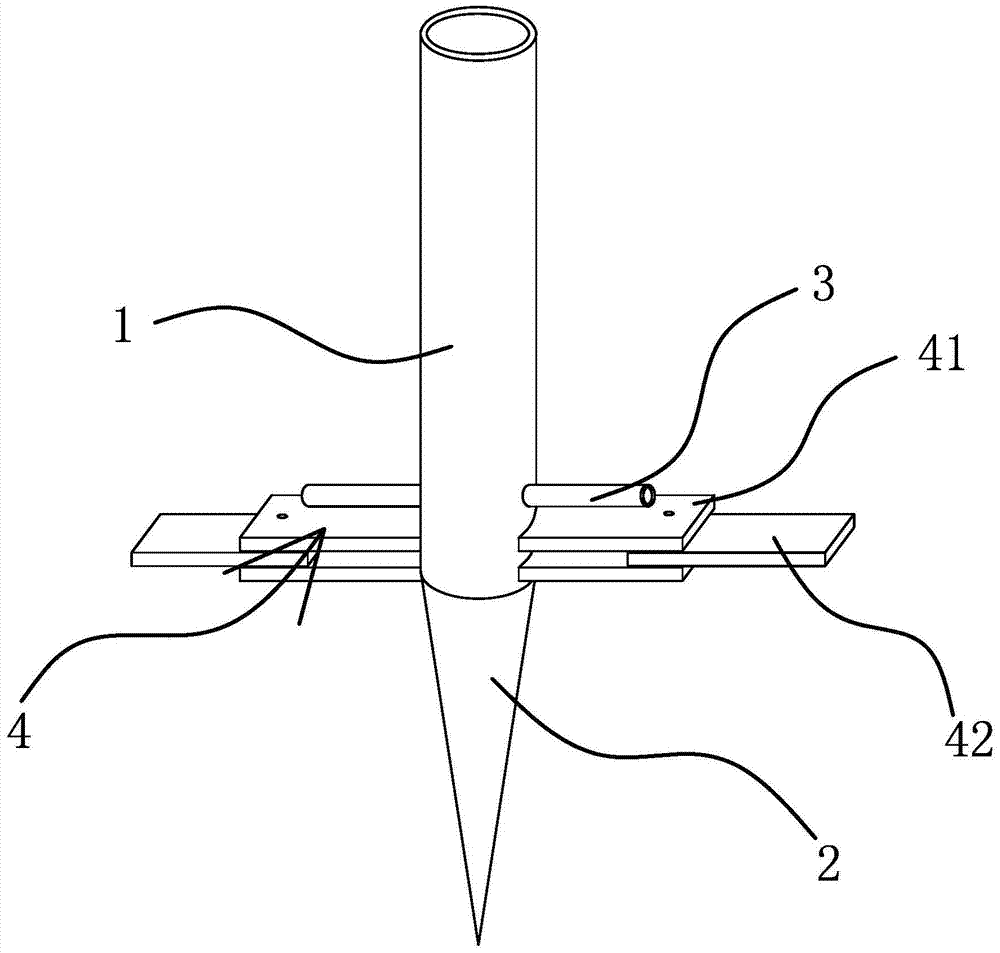
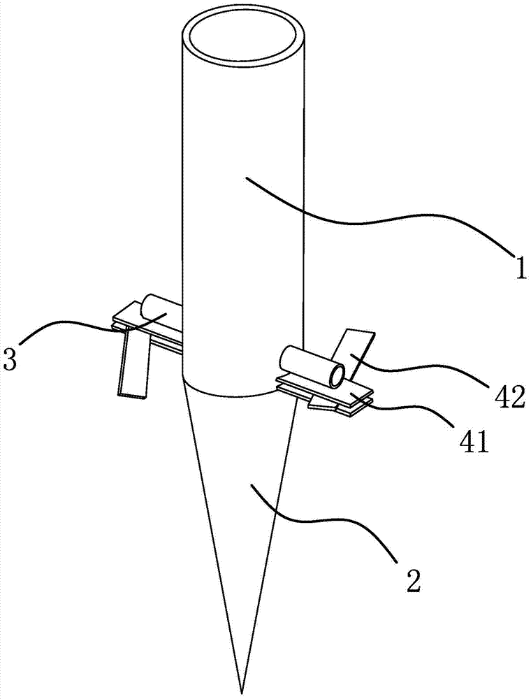
[0035]A variable-diameter stirring anchor, including a hollow anchor body 1 and a drill bit 2 fixed at the front end of the anchor body 1, the length of the anchor body 1 is 6 to 30 meters, and 15 meters are selected in this embodiment. Meter-long bolt body 1, the front end of the bolt body 1 is provided with a slurry outlet pipe 3, the bolt body 1 communicates with the slurry outlet pipe 3, and the front end of the bolt body 1 is also fixedly equipped with a stirring body 4, the first stirring The inner end of leaf 41 is fixed on the outer wall of anchor body 1, and stirring body 4 comprises the first stirring blade 41 that is fixedly connected with the pipe wall of anchor body 1 and perpendicular to the centerline of anchor body 1, and stirring body 4 Also comprise a second stirring blade 42, the first stirring blade 41 is hinged with one end of the second stirring blade 42, and the second stirring blade 42 can swing in the plane where the first stirring blade 41 blade surfac...
Embodiment 2
[0041] The content of this embodiment is roughly the same as that of the first embodiment, except that the first stirring blade 41 has only one piece.
Embodiment 3
[0043] The content of this embodiment is roughly the same as that of Embodiment 1, except that there are 2 to 5 stirring bodies 4, and all stirring bodies 4 are evenly arranged along the outer peripheral wall of the bolt body 1, and multiple stirring bodies 4 It can improve the stirring efficiency, so that the coagulant and the soil can be mixed evenly, and the multiple stirring bodies 4 are evenly distributed on the outer peripheral wall of the anchor body 1, so that the anchor body 1 is easier to maintain uniform rotation and uniform speed drilling. , Improve the construction quality.
PUM
| Property | Measurement | Unit |
|---|---|---|
| Length | aaaaa | aaaaa |
| Length | aaaaa | aaaaa |
Abstract
Description
Claims
Application Information