Turbocharger

A technology of turbocharger and transition joint, applied in machine/engine, engine components, internal combustion piston engine, etc., can solve problems such as decreased efficiency, decreased working power of impeller, increased entropy, etc., to achieve the effect of improving efficiency

Inactive Publication Date: 2014-03-26
WUXI CUMMINS TURBO TECH
View PDF5 Cites 3 Cited by
  • Summary
  • Abstract
  • Description
  • Claims
  • Application Information

AI Technical Summary

Problems solved by technology

This way when two air streams are mixed, one is a high temperature gas and the other is a low temperature gas, due to the huge temperature difference, when they mix, it will cause a huge increase in entropy, and the increase in entropy will cause a decrease in efficiency
[0009] That is to say, there are three reasons for the drop. One is that the bypass air flow no longer participates in the work. The second i

Method used


Image

  • Turbocharger
  • Turbocharger

Examples


Embodiment Construction

[0022] The specific embodiments of the present invention will be further described below in conjunction with the accompanying drawings.

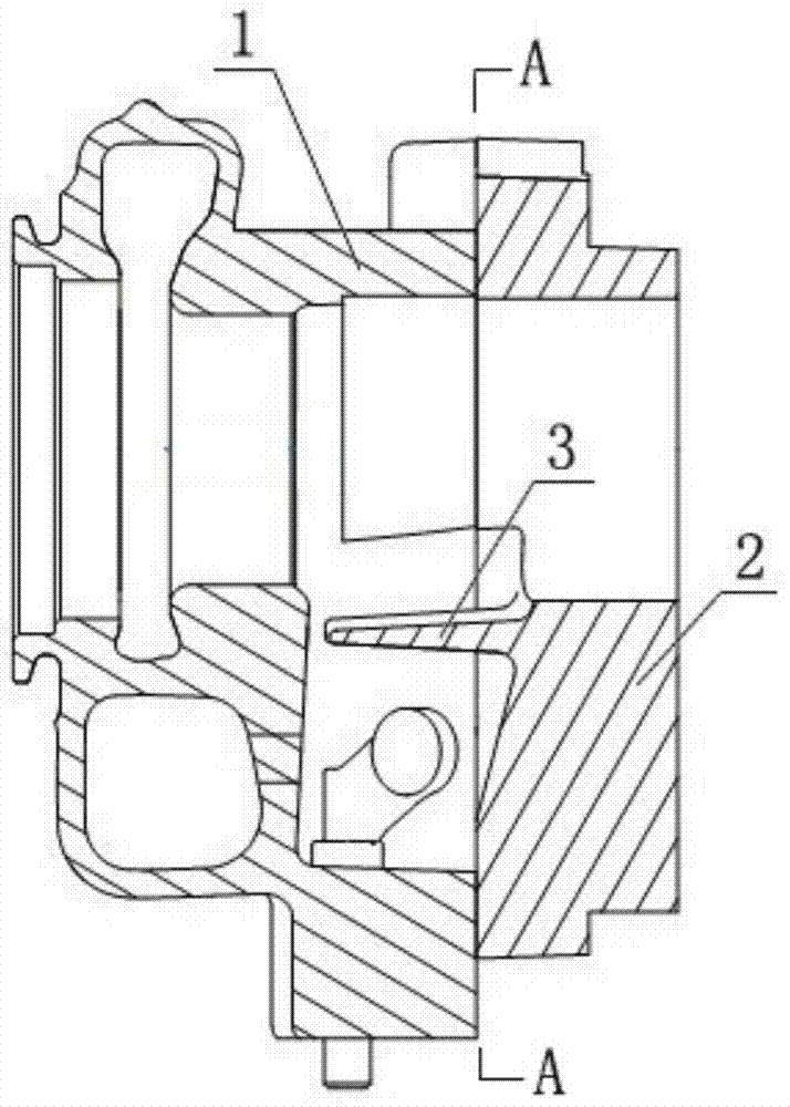
[0023] figure 1 , figure 2 , including volute 1, transition joint 2, partition wall 3, channel 4, flow channel 5, etc.

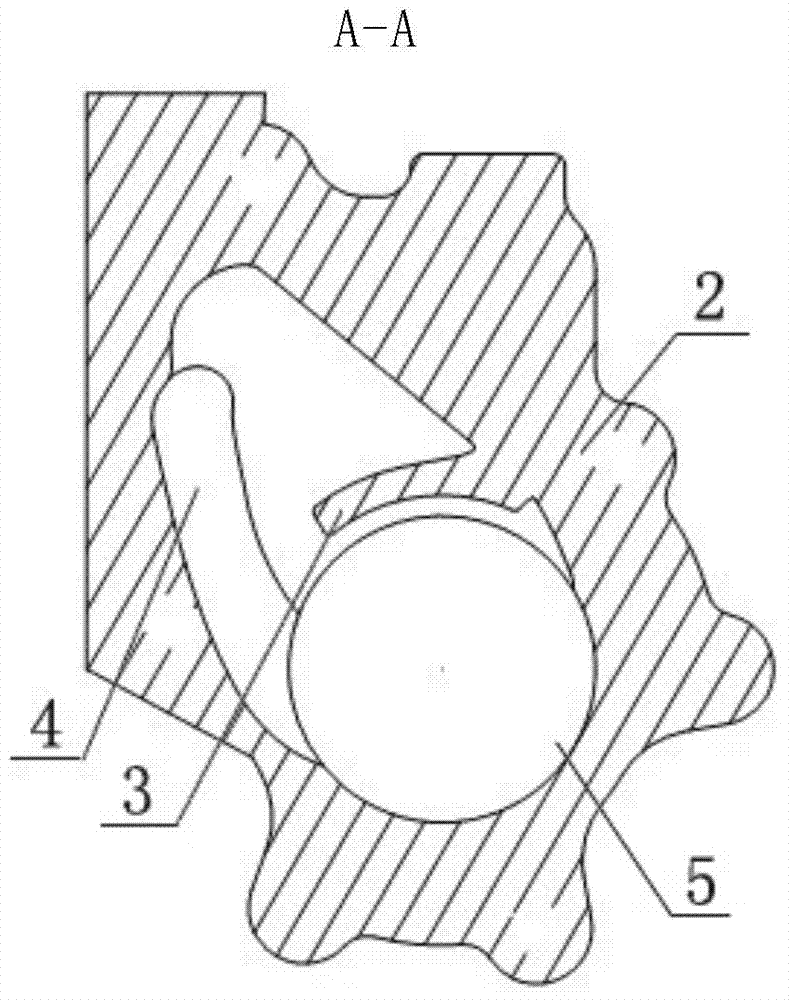
[0024] Such as figure 1 , figure 2 As shown, the present invention is a turbocharger, including a volute 1, a transition joint 2 is fastened to the mounting surface of the volute 1 to form a flow channel 5, and the inner cavity of the transition joint 2 is provided with a partition The wall 3, and the partition wall 3 extends into the flow channel 5, and a channel 4 is opened on the bottom surface of the inner cavity of the transition joint 2.

[0025] The surface of the partition wall 3 facing the main flow channel is in the shape of a circular arc transition.

[0026] The channel 4 is arranged on the side opposite to the partition wall 3 in the inner cavity of the transition joint 2 , and the channel 4 is arranged...


PUM


Abstract

The invention relates to a turbocharger. The turbocharger comprises a volute, a transition connector is fastened and connected to the installation face of the volute, a partition wall is arranged in an inner cavity of the transition connector, and a channel is formed in the bottom face of the inner cavity of the transition connector. Firstly, due to the fact that the partition wall is arranged, bypass flow and main flow can hardly be mixed, so that entropy production is reduced; in addition, due to the fact that the special channel is design, flowing of the bypass flow can be smoother compared with the flowing of the bypass flow under the condition that the special channel is not formed, turbulence intensity is lowered, and entropy production can be reduced as well; efficiency can be lowered due to entropy production, and efficiency can be lowered when entropy production is reduced. Secondly, due to the existence of the partition wall and the special channel, mixing of the bypass flow and the main flow is farther away from an impeller compared with the traditional design that no partition wall or channel is formed, and the work capacity of the impeller can be lowered although the backpressure of the impeller can still be increased. The farther the mixing position is, the smaller the backpressure is, and therefore the lowering amplitude of the work capacity is smaller.

Description

technical field [0001] The invention relates to a turbocharger. Background technique [0002] A turbocharger is an accessory of a reciprocating internal combustion engine, which can use the energy of the high-temperature and high-pressure gas discharged from the internal combustion engine to inhale more fresh air into the combustion chamber. [0003] The energy in the combustion chamber of the internal combustion engine has three kinds of consumption, one is the work done on the piston, that is, the output work of the internal combustion engine spindle; the other is the energy dissipated by heat transfer through the inner wall of the combustion chamber; the third is the energy of the exhaust gas. Under the condition of a certain fuel consumption rate, in order to allow the main shaft of the internal combustion engine to output more work, we hope that the energy in the exhaust gas discharged by it should be as small as possible, but in order to ensure that the internal combus...

Claims


Application Information

Patent Timeline
IPC IPC(8): F02B37/00F01D25/00
CPCY02T10/12
Inventor 刘志鹏
Owner WUXI CUMMINS TURBO TECH
Why Eureka
Try Eureka