A Micro Free Piston Generator with Air Intake Preheating

A generator and piston technology, applied in the field of micro-power system, can solve the problems of not fully realizing the generator and prime mover, not considering the effective emission of exhaust gas, and low electromagnetic conversion efficiency, so as to increase the exhaust gas cavity and one-way exhaust The effect of valve structure, optimization of exhaust gas discharge capacity, and avoidance of energy loss

Active Publication Date: 2016-01-20
泰州市海创新能源研究院有限公司
View PDF10 Cites 0 Cited by
  • Summary
  • Abstract
  • Description
  • Claims
  • Application Information

AI Technical Summary

Problems solved by technology

[0002] Micro-electromechanical devices require high-energy-density energy output devices to provide continuous power output, because micro-power devices that burn hydrocarbon fuels in the micro-scale space only need 10% conversion efficiency to generate electricity 6 times higher than the current best batteries. times the energy density, more and more scholars have designed and researched micro-power systems based on hydrocarbon fuel combustion; most of the existing power generation systems use the separation of the prime mover and the generator, and there are many Disadvantages, such as large volume, complex structure, low electromagnetic conversion efficiency, large energy consumption, etc.
[0003] Most of the so-called combinations of generators and prime movers disclosed at present have not fully realized the real combination of generators and prime movers. Motorized sub-motion power generation, such as patent 94112513.0: "reciprocating generator", 200420109327.4 "a reciprocating generator", WO0188353: "FREEPISTONEENGINEWITHELECTRICALPOWEROUTPUT", RU2150014: "FREE-PISTONINTERNAL-COMBUSTIONENGINEWITHLINEARACGENERATOR" utilizes belts are all like this; Magnetic pistons and solenoid coils are used as power generation components, and the power generation efficiency is too low, such as the patent US4403153: "FREE-PISTONELECTRICCURRENTGENERATOR", and the reciprocating generator with better power generation efficiency, such as the device described in the patent US3891874: "COMPENSTATEDRECIPROCATINGELECTRODYNAMICMACHINE", but the patent However, it needs to be driven by other power sources; and the patent CN1978877: "Free Piston Generator", although it overcomes some shortcomings, it ignores other shortcomings, and does not take into account the effective discharge of exhaust gas, waste heat utilization of exhaust gas, etc.

Method used


Image

  • A Micro Free Piston Generator with Air Intake Preheating
  • A Micro Free Piston Generator with Air Intake Preheating
  • A Micro Free Piston Generator with Air Intake Preheating

Examples


Embodiment Construction

[0027] The present invention will be further described below in conjunction with drawings and embodiments.

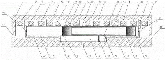
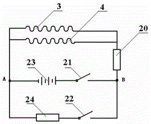
[0028] Such as figure 1 and figure 2 As shown, when in use, the battery switch 21 is first closed, and the current generated in the battery 23 is converted into alternating current through the current inverter 20, and the alternating magnetic field is generated through the left stator winding 3 and the right stator winding 4, and the alternating magnetic field acts The magnetic piston 10 makes it reciprocate, thus completing the starting work of the generator.

[0029] The magnetic piston 10 moves left and right in the alternating magnetic field, and after obtaining a certain speed, the mixed gas injector 8 is opened to start injecting the mixed gas; Figure 4 As shown, when the magnetic piston 10 moves to the right, the left-end mixed gas injector 8 is opened, and the mixed gas is injected into the left-end micro-combustion chamber cylinder 7; as Figure 5 As shown...


PUM


Abstract

The invention relates to a micro dynamical system relevant to the field of internal combustion engines and the field of electricity generation, in particular to an inlet gas preheating type micro free piston electric generator. The inlet gas preheating type micro free piston electric generator comprises magnetic pistons, a micro combustion chamber cylinder, mixed gas ejectors, intake channels, exhaust channels, a waste gas cavity, a scavenging plate, one-way exhaust valves, exciting windings, a stator, stator windings, left separation poles, right separation poles, a current inverter, switches, a storage battery and the like. The inlet gas preheating type micro free piston electric generator is characterized in that the magnetic pistons serve as not only free pistons of a micro engine but also electricity generation armatures; the waste gas cavity, the scavenging plate and the one-way exhaust valves are added to constitute an scavenging structure, and therefore the waste gas exhaust function is enhanced; the intake channels are embedded in the exhaust channels, and excess heat of waste gas is used for preheating mixed gas in the intake channels. The inlet gas preheating type micro free piston electric generator has the advantages that an internal combustion engine and an electric generator are combined organically, the structure is simplified, meanwhile, overall performance of the micro electric generator is optimized, energy loss of a mechanical mechanism moving in a reciprocating mode is reduced, and a high energy conversion rate is obtained.

Description

technical field [0001] The invention relates to a micro-power system related to the field of internal combustion engines and the field of power generation, in particular to an air intake preheating type micro-free piston generator. Background technique [0002] Micro-electromechanical devices require high-energy-density energy output devices to provide continuous power output, because micro-power devices that burn hydrocarbon fuels in the micro-scale space only need 10% conversion efficiency to generate electricity 6 times higher than the current best batteries. times the energy density, more and more scholars have designed and researched micro-power systems based on hydrocarbon fuel combustion; most of the existing power generation systems use the separation of the prime mover and the generator, and there are many Disadvantages, such as large volume, complex structure, low electromagnetic conversion efficiency, and large energy consumption. [0003] Most of the so-called c...

Claims


Application Information

Patent Timeline
Patent Type & Authority Patents(China)
IPC IPC(8): F02M31/06H02K35/02
CPCY02T10/12
Inventor 柏金王谦何志霞张彭岗吴凯
Owner 泰州市海创新能源研究院有限公司
Why Eureka
Try Eureka