
Air inlet flow guide pipe and preparation method thereof

A guide tube and intake hose technology, applied in intake muffler, mechanical equipment, combustion air/combustion-air treatment, etc., can solve the complex direction of intake guide tube, large intake resistance, bellows It can improve the NVH level, improve the noise reduction effect, and improve the assembly efficiency.

Active Publication Date: 2014-03-26
ANHUI JIANGHUAI AUTOMOBILE GRP CORP LTD
View PDF7 Cites 7 Cited by
  • Summary
  • Abstract
  • Description
  • Claims
  • Application Information

AI Technical Summary

Problems solved by technology

The air intake duct is generally arranged in the engine compartment. In order to reduce the noise of the air intake and reduce the impact of noise on the cab, it is generally necessary to add various shapes of muffler cavities to the intake duct; however, the space in the engine compartment Limited, in order to avoid the interference of related parts, this leads to the complicated orientation of the air intake guide pipe, which is inconvenient for assembly and transportation; or it is bent above 90°C, which brings difficulties to the pipeline orientation and layout design, and the air intake resistance is relatively large. affect the performance of the engine;
[0004] Although the utility model patent with the patent number 201320075739.X is also a spiral pipe corrugated structure, it only replaces steel with glass steel in the middle layer of the pipe, so its corrugated pipe cannot be bent, compressed, or stretched axially or tangentially; Importantly, the pipe has no noise reduction effect and is used on municipal drainage pipes, which is completely different from the application of automotive power auxiliary components

Method used

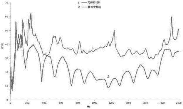
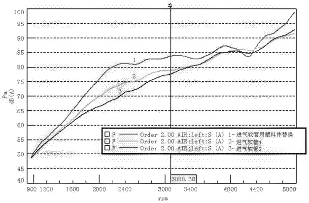
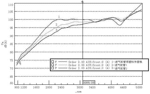

Image

  • Air inlet flow guide pipe and preparation method thereof
  • Air inlet flow guide pipe and preparation method thereof
  • Air inlet flow guide pipe and preparation method thereof

Examples


Embodiment Construction

[0034] The specific technical solutions of the present invention will be described in detail below in conjunction with the accompanying drawings and specific embodiments.

[0035] Intake guide pipe: In the car air intake system, the air intake pipe connecting the air intake port and the air filter is also called a dirty pipe; it is used to guide air into the air filter.

[0036] Such as figure 1 As shown, an air intake duct includes an air inlet 1, a first rigid pipeline 2, an intake hose 3 and a second rigid pipeline 4, and one end of the first rigid pipeline 2 is fixedly connected to the first The air inlet 1 and the other end are fixedly connected to the air intake hose 3, one end of the air intake hose 3 is connected to the first rigid pipeline 2, and the other end is connected to the second rigid pipeline 4; wherein, the air intake soft The tube 3 is a hollow pipeline with a corrugated structure formed by a porous non-woven fabric 31 and a glass filament 32 spirally woun...


PUM

PropertyMeasurementUnit
Widthaaaaaaaaaa
Diameteraaaaaaaaaa
Lengthaaaaaaaaaa

Abstract

The invention provides an air inlet flow guide pipe, which comprises an air inlet, a first rigid pipeline, an air inlet hose pipe and a second rigid pipeline, wherein one end of the first rigid pipeline is fixedly connected with the first air inlet, the other end of the first rigid pipeline is fixedly connected with the air inlet hose pipe, one end of the air inlet hose pipe is connected with the first rigid pipeline, the other end of the air inlet hose pipe is connected with the second rigid pipeline, and the air inlet pipe is a hollow pipeline which is of a corrugated structure and is formed by spirally winding and welding porous non-woven fabric and fiber fibers in an ultrasonic way. The invention also provides a preparation method of the air inlet hose pipe. The pipeline of the air inlet flow guide pipe is flexible and variable, and is automatically applicable to the clearance difference of the assembly fixing point, so the precision requirement on the assembly fixing point is low, and the assembly efficiency is improved; the contradiction between the layout space and the property requirement of the air inlet pipeline in an engine compartment can be solved by the air inlet flow guide pipe; in the premise of not needing the complicated cavity structure, the good silencing and noise degrading functions are realized, the assembly weight is reduced, and the NVH (noise, vibration and harshness) level of vehicles is improved.

Description

technical field [0001] The invention relates to the technical field of automobile auxiliary parts, in particular to an air intake guide pipe and a preparation method thereof. Background technique [0002] As NVH plays an increasingly important role in the development of cars, the noise of the air intake system is also getting more and more attention. The main sources of noise in the air intake system are: aerodynamic noise at the air intake; vibration noise caused by the fluctuation of sound waves inside the air filter; and structural radiation noise caused by insufficient rigidity of the air filter and noise reduction components. Factors affecting the noise reduction performance of the intake system mainly include: the noise reduction volume of the noise reduction components such as the air filter and the resonance cavity; the matching of different noise reduction units, such as the use of the resonance cavity unit or the expansion cavity unit, will affect the noise reducti...

Claims


Application Information

Patent Timeline
IPC IPC(8): F02M35/104F02M35/12
Inventor 胡光辉朱培杰何竹革
Owner ANHUI JIANGHUAI AUTOMOBILE GRP CORP LTD
Features
  • Generate Ideas
  • Intellectual Property
  • Life Sciences
  • Materials
  • Tech Scout
  • Unparalleled Data Quality
  • Higher Quality Content
  • 60% Fewer Hallucinations
Learn More