
Backlight module for imaging projection system

A technology of projection system and backlight module, applied in optics, electric light source, nonlinear optics, etc., can solve the problems of poor contrast ratio of large viewing angle, low utilization rate of light energy, large divergence angle of light source, etc., and achieve the effect of improving contrast ratio

Inactive Publication Date: 2014-03-26
中航华东光电有限公司
View PDF7 Cites 4 Cited by
  • Summary
  • Abstract
  • Description
  • Claims
  • Application Information

AI Technical Summary

Problems solved by technology

[0004] Traditional projectors generally use a highly collimated backlight to achieve projection display and improve light utilization, but the divergence angle of a highly collimated backlight system cannot meet the brightness viewing angle requirements of an off-center off-axis projection system
Moreover, the traditional projection system uses a lens system to converge and collimate the light emitted by the light source. Since the surface of the LED light-emitting chip has a contact surface with metal electrodes, the chip itself emits uneven light; if a convex lens is used to directly collimate or take part of the light Collimation, i.e. uniform methods of beam expansion or spatial filtering, produces a central dark spot that accentuates the inhomogeneity of its chip surface
[0005] Traditional liquid crystal (LCD) display backlight uses a diffuser plate or a diffuser film to uniformly emit light from the LED array, and converges the backlight through a prism film. This backlight technology has good uniformity and low cost, but the divergence angle of the light source is large. The energy utilization rate is low and cannot be applied to projection display systems
[0006] Combined, the black field of the liquid crystal (LCD) module is uneven, the effective viewing angle is narrow, and the contrast ratio of the large viewing angle is poor. The reason is that the liquid crystal molecules are organic rod-shaped molecules with birefringence characteristics. The greater the refraction
When the incident light rays from different angles pass through the liquid crystal cell, due to the birefringence characteristics of the liquid crystal, the difference in the effective optical retardation (△nd) of each light is caused, so that only the light incident in the normal direction can meet the dark state transmittance. The design requirement of a minimum point, which leads to an increase in the minimum transmittance and a decrease in contrast in the dark state of light that deviates from the normal direction of the display screen

Method used


Image

  • Backlight module for imaging projection system
  • Backlight module for imaging projection system
  • Backlight module for imaging projection system

Examples


Embodiment Construction

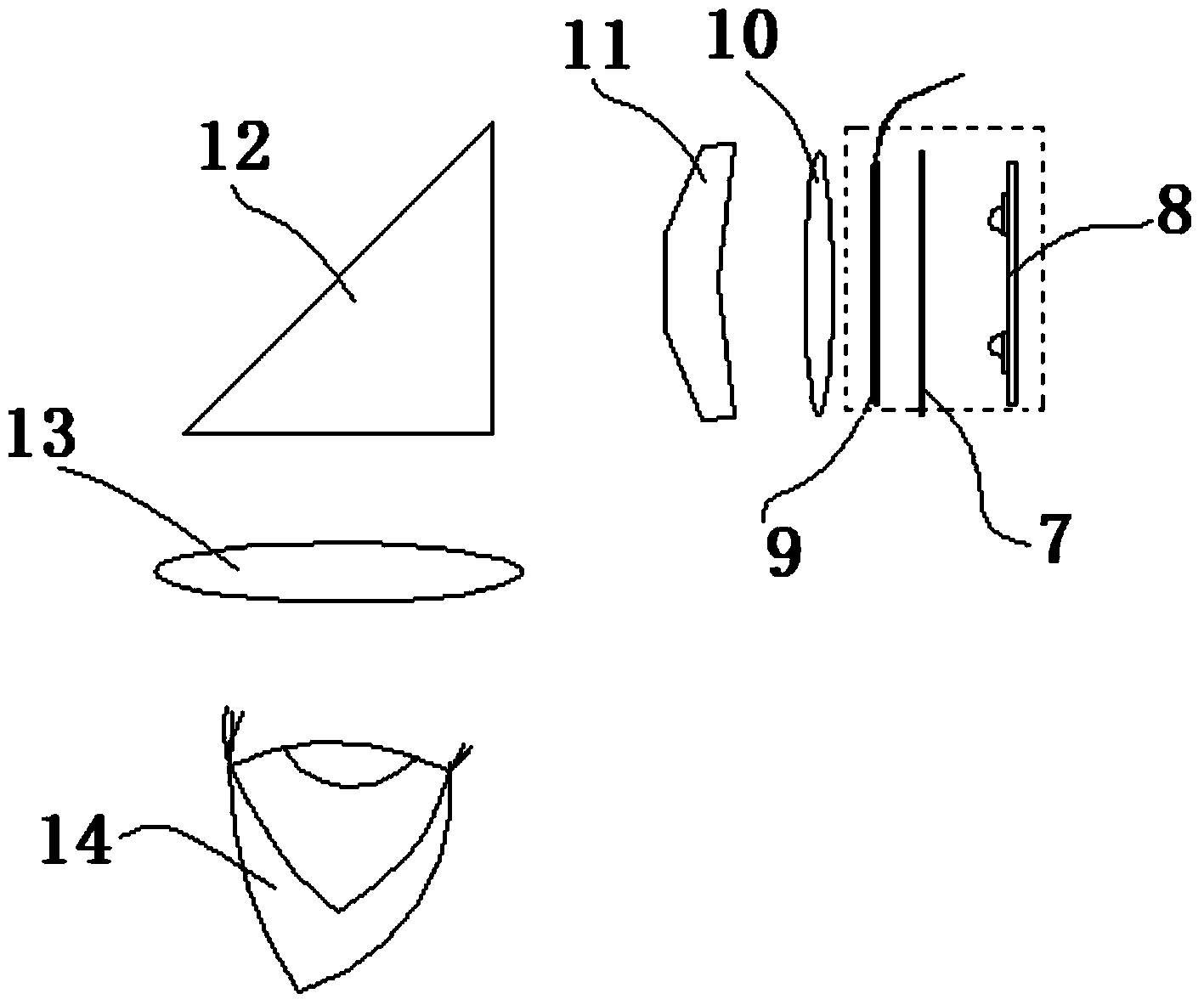
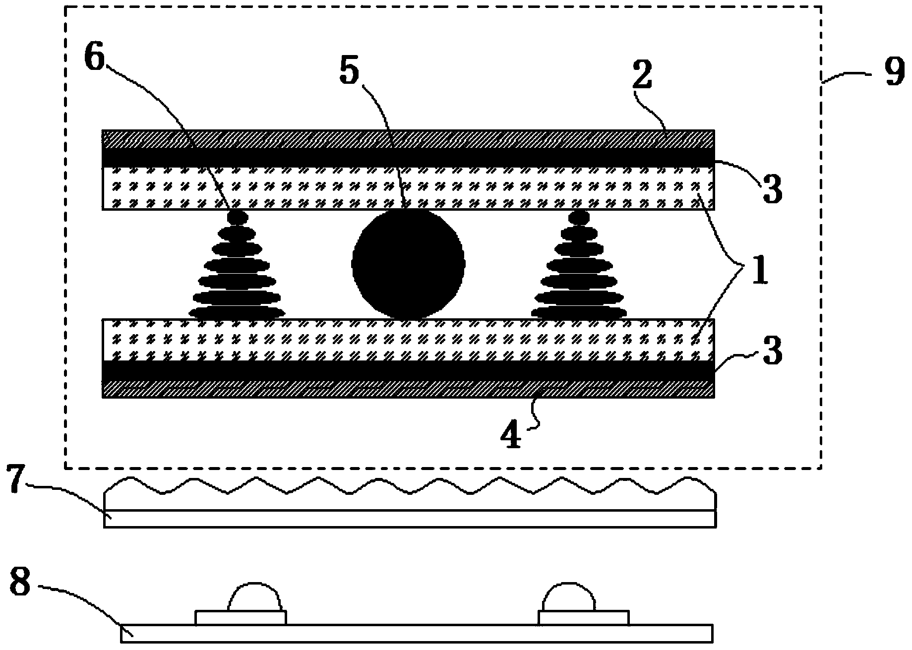
[0032] The specific implementation manner of the present invention will be described in further detail below by describing the best embodiment with reference to the accompanying drawings.

[0033] Such as figure 1 and figure 2 As shown, the backlight module for the imaging projection system includes a liquid crystal screen 9 and a backlight panel 8 , and also includes a directional diffusion film 7 arranged between the liquid crystal screen 9 and the backlight panel 8 .

[0034] The directional diffusion film 7 includes a thin film 15, and on the surface of the thin film 15 is provided a microstructure 16 composed of an arrangement of irregularly shaped lenses.

[0035] The lens rows are arranged in the form of a fly-eye lens array.

[0036] The lens size is in micron order.

[0037] The visible light transmittance of the film 15 is not less than 90%.

[0038] The film 15 has a thickness of 150±10 μm.

[0039] The film 15 is a TAC film.

[0040] The fly-eye lens array i...


PUM

PropertyMeasurementUnit
thicknessaaaaaaaaaa

Abstract

The invention discloses a backlight module for an imaging projection system. The backlight module comprises a liquid crystal display and a backlight lamp panel, and further comprises a directed diffusion diaphragm arranged between the liquid crystal display and the backlight lamp panel. A traditional diffusion type light source is replaced by a directed diffusion type light source, the LCD black field light leakage phenomenon caused by large-angle incidence of backlight rays is reduced as much as possible, and therefore the contrast ratio of the liquid crystal display is increased; the directed diffusion diaphragm can control LCD screen-leaving luminance view angle distribution including luminance asymmetrical distribution so that the requirements of an off-axis eccentric system for luminance view angles can be met. Meanwhile, the directed diffusion diaphragm has the directed diffusion focusing characteristic and has the good light uniformizing characteristic, the backlight module can replace a conventional liquid crystal backlight module composed of an ordinary diffusion diaphragm and a prism diaphragm, the structure of the backlight module is simplified, and the solar energy utilization efficiency is improved.

Description

technical field [0001] The invention relates to a backlight module, in particular to a backlight module for an imaging projection system. Background technique [0002] In recent years, with the development of science and technology, light-emitting diodes (LEDs), as a new light source technology, are widely used in liquid crystal displays, lighting equipment and other fields. Especially in recent years, with the continuous improvement of LED luminous efficiency and the development of high-power LEDs, the application fields of LEDs are also expanding, and they have begun to be used in projection display instruments. It is small in size, simple in structure, and low in price. It has great advantages in miniaturization and integration. However, the divergence angle of the LED light source is large, and the light intensity distribution is approximately Lambertian. If such a light intensity distribution is used directly without proper optical system processing, the light intensit...

Claims


Application Information

Patent Timeline
Patent Type & Authority Applications(China)
IPC IPC(8): F21S8/00F21V5/08G02F1/13357
Inventor 唐景坤刘波沈健徐立国李拓辉丁慧林
Owner 中航华东光电有限公司
Learn More