Exhaust recovery device of rotary film type thermal deaerator

A technology of thermal deoxygenation and exhaust recovery, applied in liquid degassing, chemical instruments and methods, separation methods, etc., can solve the problems of energy waste, exhaust noise, etc., to reduce noise, prevent loss, and ensure safety Effect

Inactive Publication Date: 2014-03-26
CHONGQING JUKANG BUILDING MATERIAL
View PDF0 Cites 2 Cited by
  • Summary
  • Abstract
  • Description
  • Claims
  • Application Information

AI Technical Summary

Problems solved by technology

The current rotary membrane thermal deaerator, after heating and deoxidizing, because the non-condensable gas is directly discharged to the atmosphere through the exha

Method used


Image

  • Exhaust recovery device of rotary film type thermal deaerator

Examples


Example Embodiment

[0012] detailed description

[0013] The technical solution of the present invention will be further described below in conjunction with the drawings and embodiments:

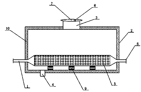
[0014] Such as figure 1 As shown, the present invention provides an exhaust gas recovery device for a rotary film thermal deaerator, which includes an exhaust pipe 1 and a horizontal water tank 2 made of stainless steel. The exhaust pipe 1 is connected to the side wall of the horizontal water tank 2, and The top of the water tank 2 is provided with a water inlet 3, a spray plate is provided under the water inlet 3, and a drain port 4 is provided at the bottom. The inner lower end of the horizontal water tank 2 is provided with a micro-perforated plate-type silencer 5 with good noise reduction effect. 5 One side is fixedly connected with the exhaust pipe 1, and the other side is connected with an exhaust port 6. An arc cover 7 is provided on the water inlet 3, and a negative pressure hole 8 is provided on the arc ...


PUM


Abstract

The invention relates to an exhaust recovery device, in particular to an exhaust recovery device of a rotary film type thermal deaerator. The exhaust recovery device comprises an exhaust pipe and a horizontal water tank connected with the exhaust pipe, a water inlet is formed in the top of the horizontal water tank, a water drainage port is formed in the bottom of the horizontal water tank, a silencer is arranged at the lower end inside the horizontal water tank, one side of the silencer is fixedly connected with the exhaust pipe, the other side of the silencer is connected with an exhaust port, an arc cover plate is arranged on the air inlet, and a negative pressure hole is formed in the arc cover plate. According to the exhaust recovery device of the rotary film type thermal deaerator with the technical scheme, noise reduction and waste steam recovery are achieved, and energy is saved.

Description

technical field [0001] The invention relates to an exhaust recovery device, in particular to an exhaust recovery device for a rotary film thermal deaerator. Background technique [0002] During the deoxygenation process of the rotary film thermal deaerator, the condensed water and supplementary water first enter the water chamber of the internal rotary membrane unit of the deaerator head of the deaerator, and are sprayed obliquely from the small hole of the membrane tube under a certain water level difference pressure. To the inner hole, a jet flow is formed. Since the inner hole is filled with rising heating steam, the water will suck in a large amount of heating steam during the jet flow movement, and a violent mixing and heating effect will be generated in a very short time, and the water temperature will be greatly increased. The rotating water continues to spin down along the inner hole wall of the membrane tube to form a tumbling water film skirt. At this time, the hea...

Claims


Application Information

Patent Timeline
IPC IPC(8): F22D1/50
Inventor 周炫张信聪
Owner CHONGQING JUKANG BUILDING MATERIAL
Why Eureka
Try Eureka