Rotary fiber Bragg grating large displacement sensor based on gear and application method thereof

A rotary, sensor technology, used in instruments, optical devices, measuring devices, etc., can solve the problem of difficult packaging of measurement deviations

Inactive Publication Date: 2014-03-26
KUNMING UNIV OF SCI & TECH
View PDF5 Cites 13 Cited by
  • Summary
  • Abstract
  • Description
  • Claims
  • Application Information

AI Technical Summary

Problems solved by technology

Due to the multi-stage gears used in the angular displacement conversion device, it is prone to measurement deviation and difficult to package

Method used


Image

  • Rotary fiber Bragg grating large displacement sensor based on gear and application method thereof
  • Rotary fiber Bragg grating large displacement sensor based on gear and application method thereof
  • Rotary fiber Bragg grating large displacement sensor based on gear and application method thereof

Examples


Embodiment approach 1

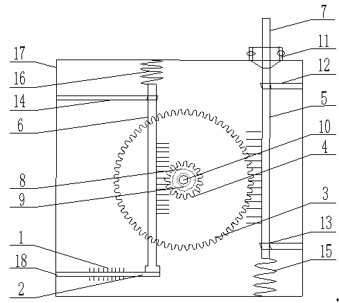
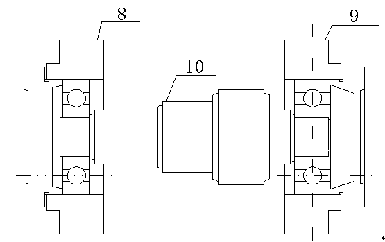
[0059] Implementation mode one: if figure 1 and 2 As shown, the present embodiment is based on the structure of the gear-rotating optical fiber Bragg grating large-displacement sensor: it includes a displacement measurement and transmission device, a displacement size conversion device and a displacement sensing device, and the above-mentioned devices are all fixed inside the metal box 17, and the displacement measurement and transmission The main body of the device is the rack I5 fixed inside the metal box 17 through the rack sleeve I12 and the rack sleeve II13. The upper end of the rack I5 extends out of the metal box 17 and is fixed by the displacement limiting sleeve 11; The structure of the conversion device is that the stepped shaft 10 is coaxially connected with the large gear 3 and the pinion 4; the main body of the displacement sensing device is the rack II 6 which is fitted through the rack bushing III 14 at the upper end and fixedly connected with the cantilever bea...

Embodiment approach 2

[0075] Implementation mode two: if figure 1 and 2 As shown, the present embodiment is based on the structure of the gear-rotating optical fiber Bragg grating large-displacement sensor: it includes a displacement measurement and transmission device, a displacement size conversion device and a displacement sensing device, and the above-mentioned devices are all fixed inside the metal box 17, and the displacement measurement and transmission The main body of the device is the rack I5 fixed inside the metal box 17 through the rack sleeve I12 and the rack sleeve II13. The upper end of the rack I5 extends out of the metal box 17 and is fixed by the displacement limiting sleeve 11; The structure of the conversion device is that the stepped shaft 10 is coaxially connected with the large gear 3 and the pinion 4; the main body of the displacement sensing device is the rack II 6 which is fitted through the rack bushing III 14 at the upper end and fixedly connected with the cantilever bea...


PUM


Abstract

The invention relates to a rotary fiber Bragg grating large displacement sensor based on a gear and an application method of the rotary fiber Bragg grating large displacement sensor, and belongs to the technical field of photoelectron measuring. The rotary fiber Bragg grating large displacement sensor comprises a displacement measuring and transferring device, a displacement conversion device and a displacement induction device; the displacement measuring and transferring device, the displacement conversion device and the displacement induction device are all fixed in a metal box; a body of the displacement measuring and transferring device is a rack I fixed in the metal box through a rack sleeve I and a rack sleeve II, and the upper end of the rack I extends out of the metal box and is fixed through a displacement limiting sleeve; the structure of the displacement conversion device is that a stepped shaft is coaxially connected with a big gear wheel and a pinion. The application method comprises the steps that a mathematical model is established in the sensor, actual measurement is performed on the sensor through the mathematical model to obtain numerical values, then, the numerical values are converted to a Bragg wavelength shift of a fiber Bragg grating, and finally the displacement measured by the displacement sensor can be calculated. In this way, real-time online monitoring of large displacement and temperature is achieved.

Description

technical field [0001] The invention relates to a gear-rotating optical fiber Bragg grating large displacement sensor and a use method thereof, belonging to the technical field of optoelectronic measurement. Background technique [0002] In recent years, accidents such as bridge collapses, tunnel collapses, and landslides along the way have occurred frequently in China. Timely and accurate grasp of crack changes and relative position slippage in civil structures makes displacement detection particularly important. At present, the existing fiber grating displacement sensors generally fix the fiber grating on various elastic beams, convert the displacement to the strain of the grating through the deformation of the beam (shrapnel), and measure the corresponding displacement by demodulating the wavelength drift of the grating. This kind of sensor has high precision, anti-electromagnetic interference, stable chemical properties and can meet distributed measurement. The disadvant...

Claims


Application Information

Patent Timeline
Patent Type & Authority Applications(China)
IPC IPC(8): G01B11/02
Inventor 李川庄君刚
Owner KUNMING UNIV OF SCI & TECH
Why Eureka
Try Eureka