
Thermal image information recording device and thermal image information recording method

A technology of information recording and thermal imaging, which is applied in the direction of image communication, TV, color TV parts, etc., and can solve the problems of cost increase and inconvenient installation of wireless tags

Inactive Publication Date: 2014-03-26
MISSION INFRARED ELECTRO OPTICS TECH
View PDF8 Cites 7 Cited by
  • Summary
  • Abstract
  • Description
  • Claims
  • Application Information

AI Technical Summary

Problems solved by technology

Those skilled in the art have been trying to solve this problem. Some methods that can be used for reference, such as patent document application number: 200410001328 disclose a camera, which can be used to notify the identified by receiving the wireless tag ID installed on the subject The information of the subject is easy to associate and record, but the installation of the wireless tag is inconvenient and the cost increases, and it is not applicable in some occasions with large electromagnetic interference; how to conveniently associate and record the thermal image file with the subject information is a problem

Method used


Image

  • Thermal image information recording device and thermal image information recording method
  • Thermal image information recording device and thermal image information recording method
  • Thermal image information recording device and thermal image information recording method

Examples


Embodiment 1

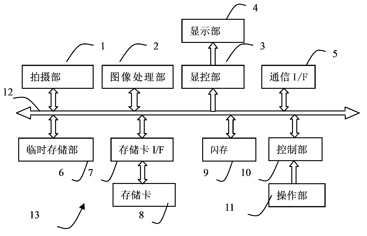
[0050] Embodiment 1 uses thermal imaging device 13 as an example of thermal image information recording device, refer to figure 1 The structure of the thermal imaging device 13 of the first embodiment will be described. figure 1It is a block diagram of the electrical structure of the thermal imaging device 13 of the embodiment.

[0051] The thermal imaging device 13 has a photographing part 1, an image processing part 2, a display and control part 3, a display part 4, a communication I / F5, a temporary storage part 6, a memory card I / F7, a memory card 8, a flash memory 9, a control part 10, The operation part 11 and the control part 10 are in charge of the overall control of the thermal imaging device 13 by connecting with the above corresponding parts through the control and data bus 12 .

[0052] The imaging unit 1 is composed of an unshown optical unit, a lens driving unit, an infrared detector, a signal preprocessing circuit, and the like. The optics section consists of i...

Embodiment approach

[0053] The image processing unit 2 is used to perform specified processing on the thermal image data obtained by the shooting unit 1. The processing of the image processing unit 2, such as correction, interpolation, false color, synthesis, compression, decompression, etc., is converted into a suitable display, Handling of data such as recording. The image processing unit 2 is used to perform prescribed processing on the thermal image data captured by the imaging unit 1 to obtain image data of infrared thermal images. For example, the image processing unit 2 performs non-uniformity correction on the thermal image data acquired by the imaging unit 1 , interpolation and other prescribed processing, perform pseudo-color processing on the thermal image data after the prescribed processing, and obtain image data of infrared thermal images; an implementation of pseudo-color processing, for example, according to the range or AD value of thermal image data (AD value) The setting range ...

Embodiment 2

[0191] This embodiment is with figure 1 In the thermal imaging device 13 with the same structure as shown, in the flash memory 9, the subject selection information used to obtain the subject information with specific information is stored, and the subject selection information obtained with other subject information is stored. Information is displayed in different ways by the control program. refer to Figure 24-Figure 25 This embodiment will be described.

[0192] refer to Figure 24 The control procedure of this reference mode will be described.

[0193] In step B01, the control unit 10 implements its control, and continuously monitors whether the user selects the information mode through the operation unit 11, and when it is detected that the user presses the mode button, it proceeds to step B02.

[0194] In step B02 , the display control unit (control unit 10 ) performs specifying processing of a predetermined number of subject information. see details Figure 18 Pro...


PUM


Abstract

The invention discloses a thermal image information display control device and a thermal image information display control method, and relates to the application fields of thermal image devices, thermal image processing devices, and infrared thermal imaging detection. According to a thermal image device in the prior art, a shooting person selects a shot object needs to be shot according to the subjective experience, so the shot object is easy to shoot mistakenly or omit. According to the invention, based on the stored shot object information, shot object selection information acquired by shot object information of a specified number is displayed while displaying an infrared thermal image, the shot object selection information acquired by the shot object information having specific information and the shot object selection information acquired by other shot object information are displayed in a distinguishing manner, or one of the shot object selection information acquired by the shot object information having specific information and the shot object selection information acquired by other shot object information is not displayed. When a user selects the shot object selection information, a corresponding reference image is displayed; so that the user can conveniently distinguish a shot object needs to be shot from shot objects does not need to be shot, and according to the reference of the reference image, the shooting quality is improved, and problems existing currently can be solved.

Description

technical field [0001] The thermal image information recording device and the thermal image information recording method of the present invention relate to thermal imaging devices and the application field of infrared detection. Background technique [0002] As a well-known technology, thermal imaging devices are widely used in the industrial and architectural fields. Currently, the thermal image files obtained by shooting are generated according to the time or serial number of the file name; for subsequent archiving and analysis, and to distinguish the thermal image files corresponding to the subject , during infrared detection, the user needs to record the information of the subject according to the recognition of the subject or the on-site nameplate. The existing common recording methods are, for example, manually recording the file name of the thermal image file and the corresponding subject with paper Information; create a folder corresponding to the subject information...

Claims


Application Information

Patent Timeline
IPC IPC(8): G01J5/10H04N5/33H04N5/232
Inventor 王浩
Owner MISSION INFRARED ELECTRO OPTICS TECH
Learn More