
Liquid flow frame assembly and flow cell

A liquid flow battery and liquid flow frame technology, which is applied in the direction of fuel cells, regenerative fuel cells, fuel cell additives, etc., can solve the problems of low capacity and poor electrical conductivity of liquid flow batteries, and achieve simple structure, improved electrical conductivity, The effect of capacity equalization

Active Publication Date: 2014-03-26
DONGFANG ELECTRIC (CHENGDU) HYDROGEN FUEL CELL TECH CO LTD
View PDF4 Cites 7 Cited by
  • Summary
  • Abstract
  • Description
  • Claims
  • Application Information

AI Technical Summary

Problems solved by technology

[0005] The present invention aims to provide a flow frame assembly and a flow battery to solve the problems of low capacity and poor electrical conductivity of the flow battery in the prior art

Method used


Image

  • Liquid flow frame assembly and flow cell
  • Liquid flow frame assembly and flow cell
  • Liquid flow frame assembly and flow cell

Examples


Embodiment Construction

[0029] The embodiments of the present invention will be described in detail below with reference to the accompanying drawings, but the present invention can be implemented in many different ways defined and covered by the claims.

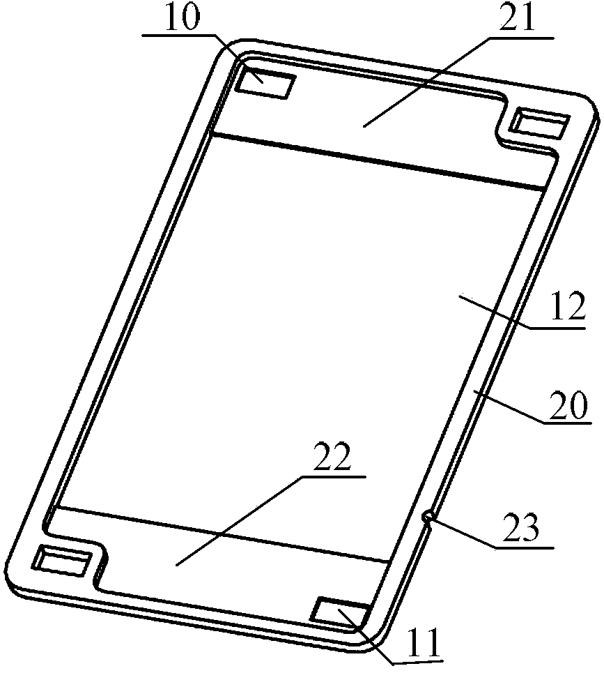
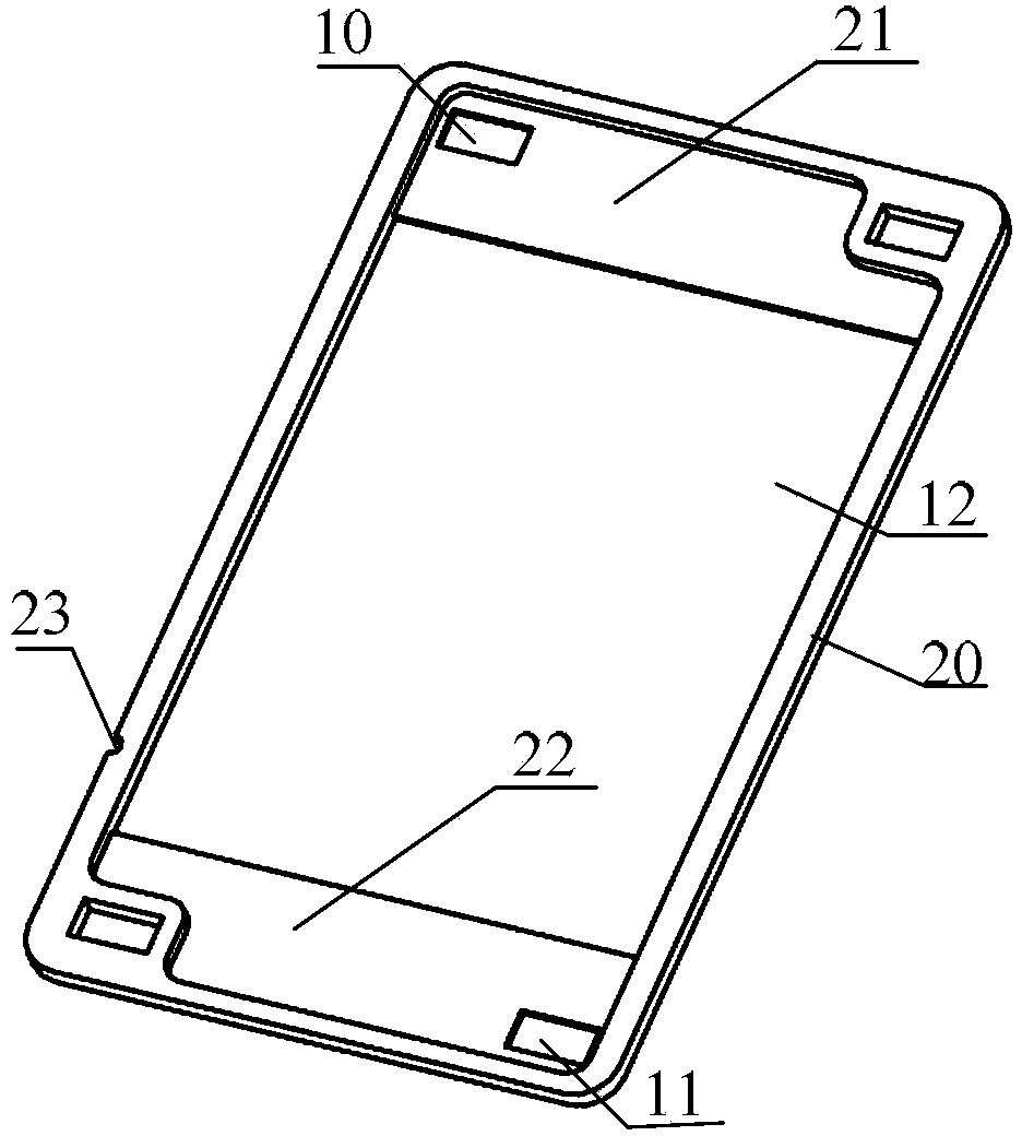
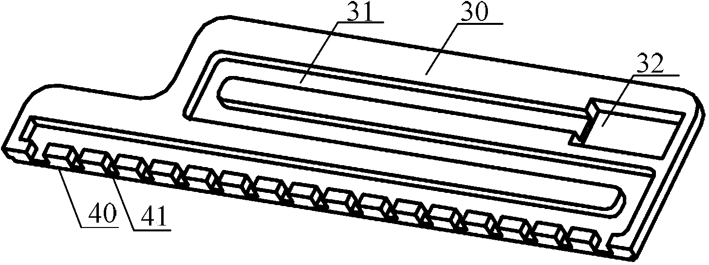
[0030] As a first aspect of the present invention, a liquid flow frame assembly is provided. Such as Figures 1 to 7 As shown, the liquid flow frame assembly has a first liquid inlet 10, a first liquid outlet 11, a flow channel and a reaction opening 12 for accommodating the electrode 60, and the first liquid inlet 10 or the first liquid outlet 11 passes through The flow channel communicates with the reaction opening 12, and the flow channel is an internal flow channel located between the two sides on opposite sides of the liquid flow frame assembly. Since the flow channel is an internal flow channel between the two sides on opposite sides of the liquid flow frame assembly, the electrolyte only flows in the liquid flow frame assembly, thereby isola...


PUM


Abstract

The invention provides a liquid flow frame assembly and a flow cell. The liquid flow frame assembly comprises a first liquid inlet, a first liquid outlet, a flow channel and reaction openings accommodating electrodes, the first liquid inlet or the first liquid outlet are communicated with the reaction openings via the flow channel, and the flow channel is an internal channel disposed between two opposite sides of the liquid flow frame assembly. Due to the fact that the flow channel is an internal channel disposed between two opposite sides of the liquid flow frame assembly, electrolyte can flow only in the liquid flow frame assembly, so that electrolyte is separated from an ion exchange membrane, the ion exchange between anolyte / catholyte and the ion exchange membrane is avoided, and thus the capacity equalization of anolyte and catholyte are guaranteed, the capacity of the flow cell is guaranteed, and the conductive performance of the flow cell is guaranteed. Also, the liquid flow frame assembly provided by the invention has the characteristics of simple structure and low manufacture cost.

Description

technical field [0001] The present invention relates to the technical field of flow batteries, and more specifically, to a flow frame assembly and a flow battery. Background technique [0002] A flow battery stack in the prior art includes a plurality of flow batteries stacked one after the other. [0003] The liquid flow battery in the prior art includes an ion exchange membrane, an electrode, a liquid flow frame body and a bipolar plate. Between the pole plates, the flow channel of the liquid flow frame body is set toward the side of the ion exchange membrane. [0004] When the flow battery is working, the electrolyte needs to flow into the reaction opening through the flow channel, so the positive and negative electrode electrolytes fully contact with the ion exchange membrane when flowing through the flow channel to perform ion exchange, resulting in a decrease in the capacity of the positive and negative electrode electrolytes. Imbalance leads to a decrease in the cap...

Claims


Application Information

Patent Timeline
Patent Type & Authority Applications(China)
IPC IPC(8): H01M8/18H01M8/02H01M8/04H01M8/0273H01M8/0276H01M8/04276
CPCY02E60/528H01M8/02H01M8/0273H01M8/18Y02E60/50Y02P70/50
Inventor 殷聪汤浩李扬刘志伟
Owner DONGFANG ELECTRIC (CHENGDU) HYDROGEN FUEL CELL TECH CO LTD
Learn More