Battery system control method

The technology of a storage battery system and a control method, which is applied in the field of control of the storage battery system, can solve problems such as increased communication speed, difficulty in applying a balance control method, and difficult wiring of the storage battery controller 208, and achieves the effect of reducing the amount of data

Inactive Publication Date: 2014-03-26
HITACHI LTD
View PDF6 Cites 2 Cited by
  • Summary
  • Abstract
  • Description
  • Claims
  • Application Information

AI Technical Summary

Problems solved by technology

[0007] The balance control method disclosed in the above-mentioned Patent Document 1 is used to eliminate the deviation between the cells and the battery packs respectively, but in order to implement the balance control of the battery system, two kinds of discharge circuits are required to be connected in parallel with the cells and the battery packs respectively.
In addition, since a voltage equivalent to the voltage of the battery pack is applied to the module discharge circuit 206 connected in parallel to the battery pack, it is necessary to secure an insulation distance from the peripheral circuit, and it is difficult to reduce the size of the board circuit.
Furthermore, in the method of Patent Document 1, it is necessary to transmit all the cell voltage information to the higher-level battery controller 208. In a large-scale storage battery system that handles a plurality of battery packs, the required communication speed increases, and the information to the storage battery The wiring of the controller 208 becomes difficult, and there is a problem that it is difficult to apply the above-mentioned balance control method.

Method used


Image

  • Battery system control method
  • Battery system control method
  • Battery system control method

Examples


Embodiment 1

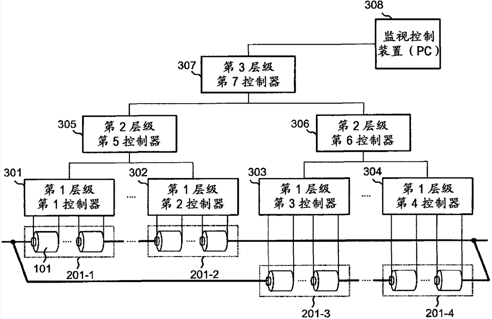
[0073] In order to illustrate the hierarchical control battery system shown in this embodiment, in image 3 A conceptual diagram of a battery system composed of three levels is shown in .

[0074] The first to fourth assembled batteries 201-1 to 201-4 are formed by connecting a plurality of assembled batteries 101 in series, in parallel, or in parallel in series. In order to equalize the voltage among the battery cells 101, the first-level controllers 301-304 are respectively connected to the first to fourth assembled batteries 201-1-201-4, and monitor the voltage of each battery cell 101 to perform balance control. The second-level controller acquires voltage information from a plurality of first-level controllers, and issues a balance control instruction to the first-level controllers. The third-level controller acquires voltage information from a plurality of second-level controllers, and instructs the second-level controllers to perform balance control.

[0075] A monito...

Embodiment 2

[0098] A balance control method applicable to the structure of the first embodiment will be described.

[0099] Generally, in a storage battery system, it is necessary to inform the user of the current charging rate. Even when there is variation in the state of charge of the battery cells, it is important to know the state of the current average charge rate of the storage battery system as a reference for considering the remaining charge capacity and the remaining discharge capacity. The average charging rate of the storage battery system can be calculated from the average voltage of all the cells, whereby the controllers of the hierarchically controlled storage battery system transmit the average voltages of the respective managed cell groups to the higher-level controllers.

[0100] In the second embodiment, the balance control in the case of transferring the average voltage of the cell to the upper level and the calculation method of the discharge instruction are described....

Embodiment 3

[0114] A balance control method applicable to the structure of the first embodiment will be described.

[0115] In the third embodiment, the control method and the calculation method of the discharge instruction are described in which the minimum voltage value among the representative voltage values ​​collected from the lower level is used as the reference voltage of the balance control while transferring the average voltage of the cell to the upper level. Figure 8 A flow chart of the balance control of the third embodiment is shown.

[0116] When the nth level controller manages m nth level controllers, the nth level controller obtains the representative voltage information (V (n-1,1) , V (n-1,2) ,...,V (n-1,m) ) (step S801). When the controller is the first layer (n=1), the voltage obtained from the n-1th layer means the cell voltage.

[0117] At this time, the minimum value of the m representative voltage information collected from the n-1th level is set as the judgmen...


PUM


Abstract

The invention provides a battery system control method. If a battery system becomes a large-scale system, all of the unit voltage information is collected to a controller for controlling a battery so as to realize the equalization of unit voltages, so that necessary communication speed has to be improved and communication wiring to the controller has to be increased. The entire voltage of batteries is transmitted to a higher-ranking controller as information. The higher-ranking controller gives a discharge instruction or the like to a lower-ranking controller having a voltage higher than those of the other controllers. Thus, voltage variation of the respective batteries is balanced.

Description

technical field [0001] The present invention relates to a control method of a storage battery system composed of a plurality of storage batteries, and more particularly to a control method of a storage battery system for equalizing the state of charge among the storage batteries. Background technique [0002] From the standpoint of power system stabilization and smart grid, it is being considered to attach a large-scale storage battery system to the power system and power plant. In order to obtain the required output and capacity of the storage battery system, a plurality of battery cells are connected in series and in parallel. When charging and discharging the battery system, the same current flows through the battery cells connected in series. Thus, as long as all the battery cells have the same characteristics, no variation will occur in the battery voltage. However, in actuality, in the manufacture of battery cells, there are variations in internal resistance, battery...

Claims


Application Information

Patent Timeline
Patent Type & Authority Applications(China)
IPC IPC(8): H01M10/42H01M10/44H01M10/48H02J7/00H02J7/02
CPCH01M10/482H01M10/441H01M2010/4271H01M2010/4278H02J7/0014H02J7/0016H01M10/425Y02E60/10
Inventor 竹内隆三浦政宏寺田崇秀
Owner HITACHI LTD
Why Eureka
Try Eureka