Combined heat dissipation device of power battery pack

A technology for power battery packs and cooling devices, which is applied to secondary batteries, circuits, electrical components, etc., can solve the problems of limited battery pack space, slow heat dissipation, slow cooling speed, etc., and achieve compact and narrow volume and wide application range , the effect of ensuring uniformity

Inactive Publication Date: 2014-03-26
SOUTH CHINA UNIV OF TECH
View PDF5 Cites 40 Cited by
  • Summary
  • Abstract
  • Description
  • Claims
  • Application Information

AI Technical Summary

Problems solved by technology

When the vehicle is in different driving conditions such as high speed, low speed, acceleration, deceleration, etc., the battery will be discharged at different rates and generate a lot of heat. In addition, the space of the battery pack is limited when the vehicle is designed, resulting in slow heat dissipation during use. , the battery temperature is very easy to rise
Excessively high temperature will reduce the capacity, life and energy efficiency of the battery. If the heat is not dissipated in time at high temperature, it will lead to thermal runaway. In severe cases, there is a risk of violent expansion and explosion
[0004] At present, the thermal management of power batteries has attracted extensive attention from many battery manufacturers and experts. The air-cooled heat dissipation and ventilation method is generally used in the market, but this method has a slow cooling speed and poor temperature distribution uniformity among battery cells. The safe operation of the power battery is very unfavorable

Method used


Image

  • Combined heat dissipation device of power battery pack
  • Combined heat dissipation device of power battery pack
  • Combined heat dissipation device of power battery pack

Examples


Embodiment

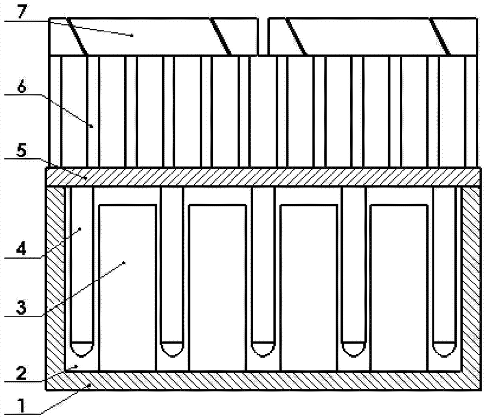
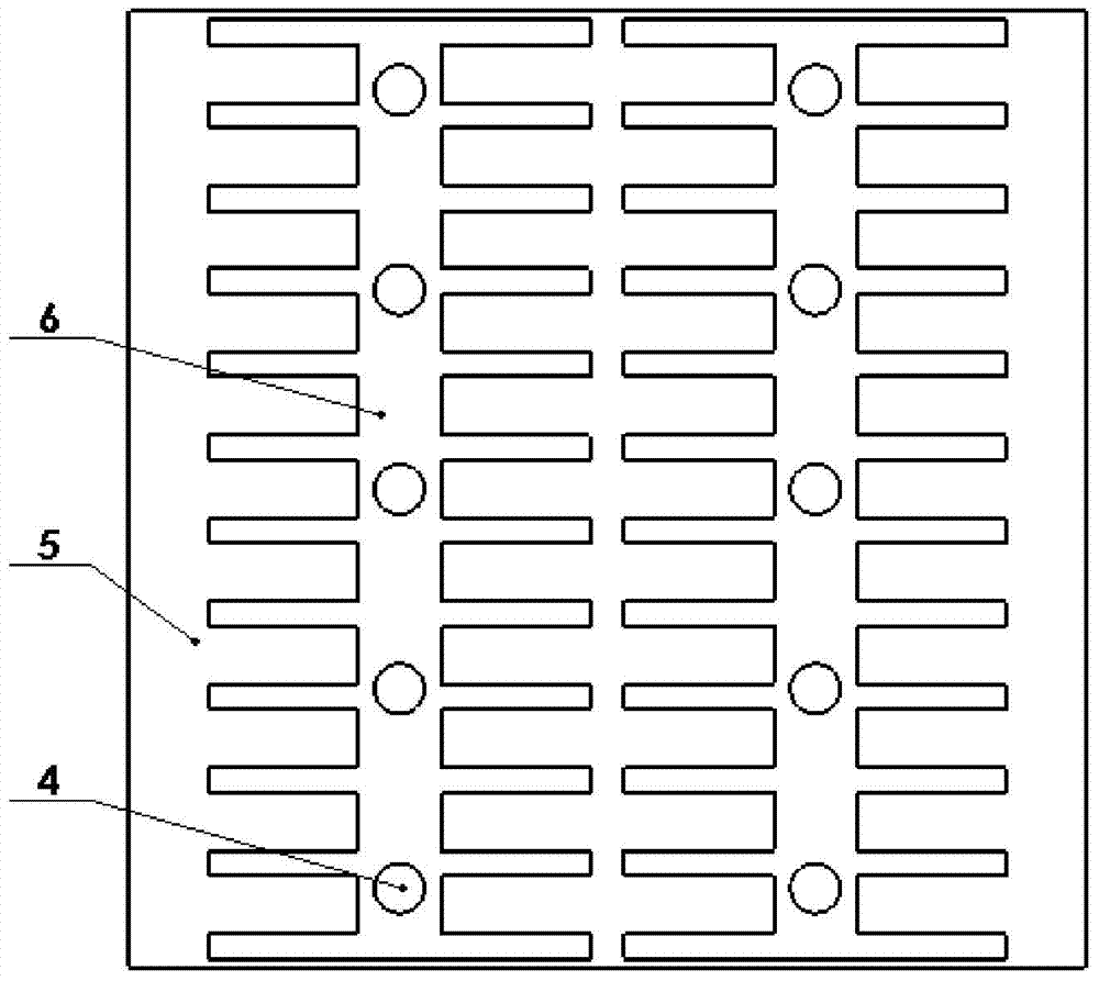
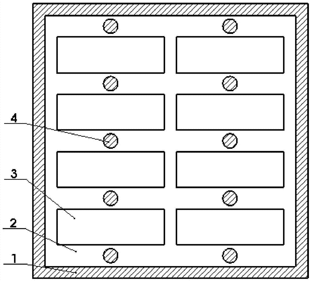
[0022] Such as Figures 1 to 3 shown. The composite cooling device of the power battery pack of the present invention includes a box body 1, a cover plate 5, a single battery 3, a phase change material layer 2, a porous surface heat pipe 4, a cooling fin 6, and a fan 7; A battery pack composed of single cells 3; there is a gap between each adjacent battery cell, and a phase change material layer 2 is filled in the gap, and a porous surface heat pipe 4 is embedded in the phase change material layer 2, and the porous surface heat pipe 4 is connected to There is a liquid cooling working medium, and the heat sink 6 is installed on the cover plate 5 , the porous surface heat pipe 4 is connected with the heat sink 6 , the cover plate 5 is sealed and matched with the box body 1 , and the fan 7 is installed on the top of the heat sink 6 .

[0023] Such as Figure 4 shown. The porous surface heat pipe 4 is divided into an evaporation end 8 and a condensation end 9, the evaporation e...


PUM


Abstract

The invention discloses a combined heat dissipation device of a power battery pack. The combined heat dissipation device comprises a box body, a cover plate, battery cells, phase change material layers, porous surface heat pipes, radiating fins and fans, wherein the battery pack comprising the plurality of battery cells is arranged in the box body; a gap is formed between every two adjacent battery cells and filled with the phase change material layer; the porous surface heat pipes are embedded into the phase change material layers and filled with liquid cooling working mediums; the radiating fins are mounted on the cover plate; the porous surface heat pipes are connected with the radiating fins; the cover plate is in seal fit with the box body; the fans are mounted at the top ends of the radiating fins. Heat generated by the battery pack is stored through the phase change material layers, and the heat in the phase change material layers is transferred to the radiating fins through the porous surface heat pipes and finally guided to an external environment; the number of started fans is decided according to the heat generated by the battery pack to forcedly dissipate the heat so as to keep the original temperature of a battery, prevent the temperature of the battery from being increased due to the rapidly increased heat generated by the battery pack, improve the safety of the battery and prolong the service life of the battery.

Description

technical field [0001] The invention relates to heat dissipation technology for power batteries of electric vehicles, in particular to a composite heat dissipation device for power battery packs. Background technique [0002] Energy and the environment have become the most concerned issues in the world at present. The traditional conventional internal combustion engine fueled by gasoline or diesel has low thermal efficiency, which not only causes energy waste and energy crisis, but also brings serious environmental pollution and environmental degradation. However, electric vehicles have received great attention due to many advantages such as energy saving, environmental protection, use of multiple energy sources, and low noise. [0003] As a key component of an electric vehicle, the performance of the battery directly affects the operation of the electric vehicle, and temperature is an important factor affecting the performance of the power battery. When the vehicle is in d...

Claims


Application Information

Patent Timeline
Patent Type & Authority Applications(China)
IPC IPC(8): H01M10/613H01M10/625H01M10/6551H01M10/6552H01M10/6563H01M10/659
CPCY02E60/10
Inventor 汤勇陈维陆龙生胡忠海曾健
Owner SOUTH CHINA UNIV OF TECH
Why Eureka
Try Eureka