Check patentability & draft patents in minutes with Patsnap Eureka AI!

Microstrip patch antenna

A microstrip patch antenna and radiating patch technology, applied in the field of metamaterials, can solve the problems of high cost and large loss, and achieve the effects of low cost, light weight and good gain

Active Publication Date: 2014-03-26
KUANG CHI INST OF ADVANCED TECH
View PDF5 Cites 13 Cited by
  • Summary
  • Abstract
  • Description
  • Claims
  • Application Information

AI Technical Summary

Problems solved by technology

[0003] This type of microstrip patch antenna usually uses FR-4 epoxy resin plate or F4B composite material as the metamaterial support plate, and the loss of the microstrip patch antenna with FR-4 epoxy resin plate as the metamaterial support plate is slightly Some are big, usually around 10 -2 This has a great influence on the radiation efficiency and gain of the patch antenna; the radiation efficiency and gain of the microstrip patch antenna with F4B composite material as the metamaterial support plate are relatively better, but relatively Said the cost is much higher

Method used


Image

  • Microstrip patch antenna
  • Microstrip patch antenna
  • Microstrip patch antenna

Examples


Embodiment Construction

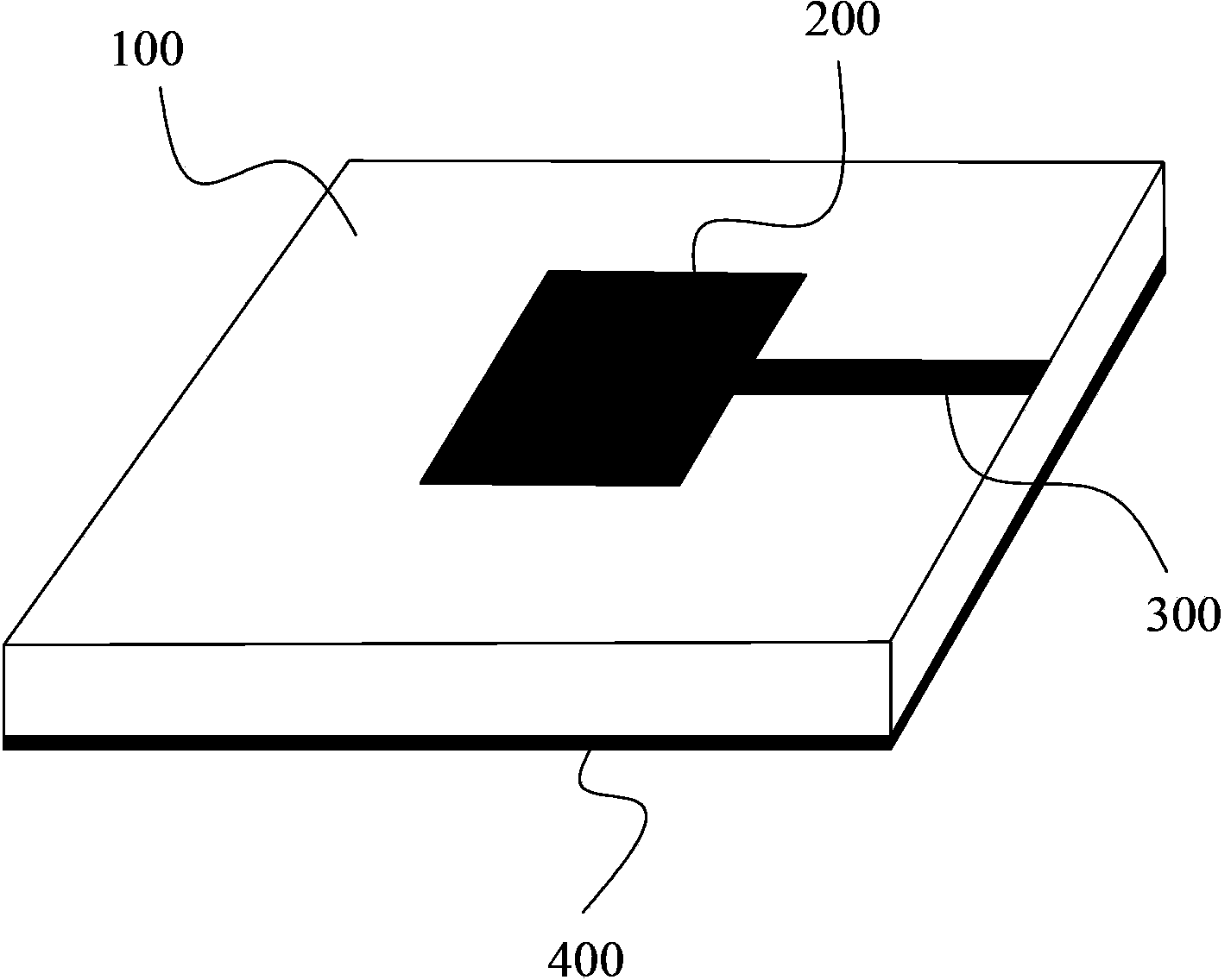
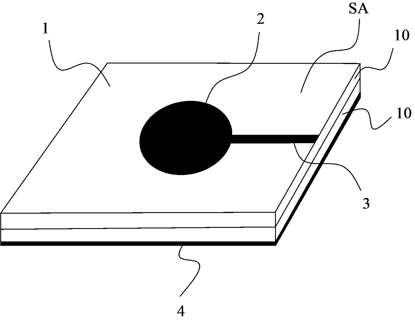
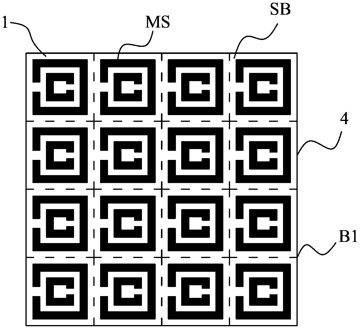
[0029] Such as Figures 2 to 3 As shown, the present invention provides a microstrip patch antenna, comprising a metamaterial support plate 1, a radiation patch 2 arranged on the surface SA of one side of the metamaterial support plate 1, and a feeder connected to the radiation patch 2 3 and the grounding plate 4 arranged on the other side surface SB of the metamaterial support plate 1, the ground plate 4 includes at least one conductive microstructure MS; the metamaterial support plate 1 includes at least one metamaterial sheet 10, such as Figures 6 to 7 As shown, each metamaterial sheet 10 includes a first dielectric substrate 11, a second dielectric substrate 12, and a plurality of artificial microstructures 13 interposed between the first dielectric substrate 11 and the second dielectric substrate 12, Figure 6 In order to express the layer structure of each metamaterial sheet, the layers formed by the multiple artificial microstructures 13 shown are represented by hatchi...


PUM


Abstract

The invention relates to a microstrip patch antenna which comprises a metamaterial support plate, a radiation patch, a feeder line and an earth plate, wherein the radiation patch is arranged on the surface of one side of the metamaterial support plate, and the feeder line is in feed connection with the radiation patch; the earth plate is arranged on the surface of the other side of the metamaterial support plate; the metamaterial support plate comprises at least one metamaterial slice, and each metamaterial slice comprises a first dielectric substrate, a second dielectric substrate and a plurality of artificial microstructures clamped between the first dielectric substrate and the second dielectric substrate; the earth plate comprises at least one conductive microstructure. According to the microstrip patch antenna, the traditional all-copper earth plate is replaced with at least one conductive microstructure, and the traditional dielectric substrate is replaced wtih the metamaterial support plate. The microstrip patch antenna has the advantages of good gain and low cost.

Description

technical field [0001] The invention relates to the field of metamaterials, more specifically, to a microstrip patch antenna. Background technique [0002] Traditional microstrip patch antennas such as figure 1 As shown, it includes a metamaterial support plate 100, a radiation patch 200 arranged on one side surface of the metamaterial support plate 100, a feeder 300 connected to the radiation patch 200, and the other side of the metamaterial support plate 100. The full copper ground plate 300 on the surface is equivalent to the area of ​​the metamaterial support plate 100 . [0003] This type of microstrip patch antenna usually uses FR-4 epoxy resin plate or F4B composite material as the metamaterial support plate, and the loss of the microstrip patch antenna with FR-4 epoxy resin plate as the metamaterial support plate is slightly Some are big, usually around 10 -2 This has a great influence on the radiation efficiency and gain of the patch antenna; the radiation effici...

Claims


Application Information

Patent Timeline
Patent Type & Authority Applications(China)
IPC IPC(8): H01Q9/04H01Q1/38H01Q1/48H01Q13/08
Inventor 刘若鹏季春霖岳玉涛何方龙
Owner KUANG CHI INST OF ADVANCED TECH
Features
  • R&D
  • Intellectual Property
  • Life Sciences
  • Materials
  • Tech Scout
  • Unparalleled Data Quality
  • Higher Quality Content
  • 60% Fewer Hallucinations
Learn More