Thyristor trigger circuit for three-phase input rectifying circuit of frequency converter

A technology of input rectification and trigger circuit, applied in the field of frequency converter, can solve problems such as increasing the cost of frequency converter, and achieve the effect of reducing cost

Active Publication Date: 2014-03-26
WISDRI WUHAN AUTOMATION
View PDF4 Cites 1 Cited by
  • Summary
  • Abstract
  • Description
  • Claims
  • Application Information

AI Technical Summary

Problems solved by technology

But it needs to configure an independent trigger circuit for the 6 thyristors, and the control of the conduction angle of the power-on requires the participation of a complex control circuit, and the use of 6 controllable devices increases the cost of the inverter

Method used


Image

  • Thyristor trigger circuit for three-phase input rectifying circuit of frequency converter
  • Thyristor trigger circuit for three-phase input rectifying circuit of frequency converter
  • Thyristor trigger circuit for three-phase input rectifying circuit of frequency converter

Examples


Embodiment Construction

[0023] The present invention will be further described below in conjunction with specific examples and accompanying drawings.

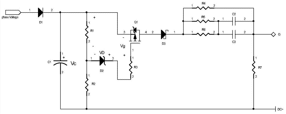
[0024] figure 2 It is a structural diagram of a thyristor trigger circuit according to an embodiment of the present invention, which includes a fast recovery diode D1, a charging capacitor C1, a MOSFET Q1, a MOSFET gate drive adjustment circuit, and a thyristor drive circuit; the input terminal of the trigger circuit inputs a phase voltage, a phase voltage After the fast recovery diode D1 is connected to the positive pole of the charging capacitor C1, the positive pole of the charging capacitor C1 is connected to the source of the MOSFET Q1, the drain of the MOSFET Q1 is connected to the gate G of the thyristor to be triggered through the thyristor driving circuit, and the charging capacitor C1 The negative electrode is respectively connected to the cathode of the thyristor to be triggered and the positive bus bar of the inverter rectifier circuit, a...


PUM


Abstract

The invention provides a thyristor trigger circuit for a three-phase input rectifying circuit of a frequency converter. The thyristor trigger circuit comprises a fast recovery diode, a charging capacitor, an MOSFET (Metal-Oxide-Semiconductor Field Effect Transistor), an MOSFET grid drive adjusting circuit and a thyristor driving circuit. A phase voltage is input at the input end of the trigger circuit, the phase voltage is connected with an anode of the charging capacitor after passing through the fast recovery diode, the anode of the charging capacitor is connected with a source electrode of the MOSFET, a drain electrode of the MOSFET is connected with a door electrode of a thyristor to be triggered through the thyristor driving circuit, a cathode of the charging capacitor is respectively connected with a cathode of the thyristor to be triggered and a positive bus of the rectifying circuit of the frequency converter, and the MOSFET grid drive adjusting circuit is arranged between the charging capacitor and a grid electrode of the MOSFET. The thyristor trigger circuit disclosed by the invention is used for the three-phase input rectifying circuit, so that the scheme is more simple and practical, and the cost is reduced.

Description

technical field [0001] The invention belongs to the field of frequency converters, and in particular relates to a thyristor trigger circuit for a three-phase input rectification circuit of a frequency converter. Background technique [0002] There are many ways to realize the three-phase input rectification circuit of the frequency converter. The first is that the six power semiconductor devices of the rectifier circuit are uncontrollable diodes. This circuit is simple and practical, and does not require additional trigger circuits and signal conditioning and control circuits. But its problem is that the power-on buffer of the rectifier bridge is not easy to realize, and it is necessary to add a large main contactor and a small auxiliary contactor to the three-phase input of the rectifier bridge. When the rectifier is powered on and buffered, the auxiliary contactor charges the three-phase power supply to the bus link of the inverter through the buffer resistor. After charg...

Claims


Application Information

Patent Timeline
Patent Type & Authority Applications(China)
IPC IPC(8): H02M1/06H02M7/219
Inventor 余骏张江涛王国强康现伟王胜勇
Owner WISDRI WUHAN AUTOMATION
Why Eureka
Try Eureka