
Integrated high-speed punch bed

A high-speed punch, integrated technology, applied in the direction of press, engine components, engine lubrication, etc., can solve the problems of complex structure, poor oil return, easy eccentricity of the crankshaft, etc., to achieve good overall rigidity and smooth oil return.

Active Publication Date: 2016-01-13
苏州欧利锦高速精密冲床科技有限公司
View PDF6 Cites 0 Cited by
  • Summary
  • Abstract
  • Description
  • Claims
  • Application Information

AI Technical Summary

Problems solved by technology

Due to the influence of the assembly process, the bed structure is not compact enough and the overall rigidity is poor
Due to assembly errors, especially when there are multiple crankshaft bearing seats on the bed of a large machine, the crankshaft is easy to eccentric, and the vibration of the crankshaft affects the accuracy
[0003] In high-speed punching machines, each lubricating part uses rubber hoses and joints to guide the lubricating oil back to the oil tank. This oil return method has a complex structure and many plug-in points, which may easily cause oil leakage and poor oil return.
Exposed conduits are also prone to breakage and poor functioning
[0004] In high-speed punching machines, the return oil is directly returned to the oil tank, and the unevenness of cold and heat in the oil tank and local overheating caused by the stratification of cold and heat will reduce the accuracy of the machine tool

Method used


Image

  • Integrated high-speed punch bed
  • Integrated high-speed punch bed
  • Integrated high-speed punch bed

Examples


Embodiment Construction

[0019] Below in conjunction with the embodiment shown in the accompanying drawings, the present invention is described in detail as follows:

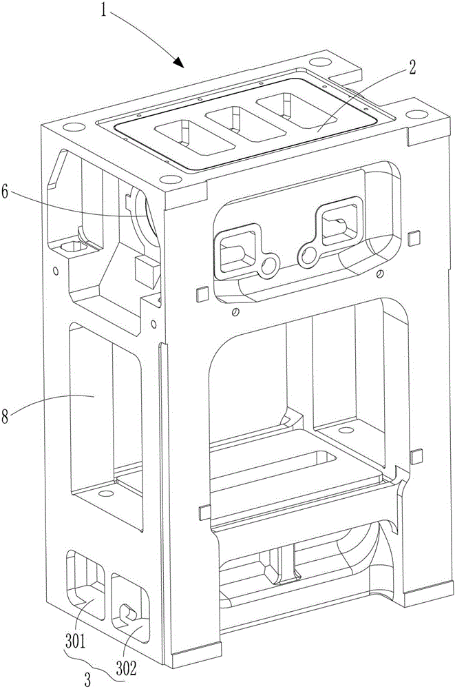
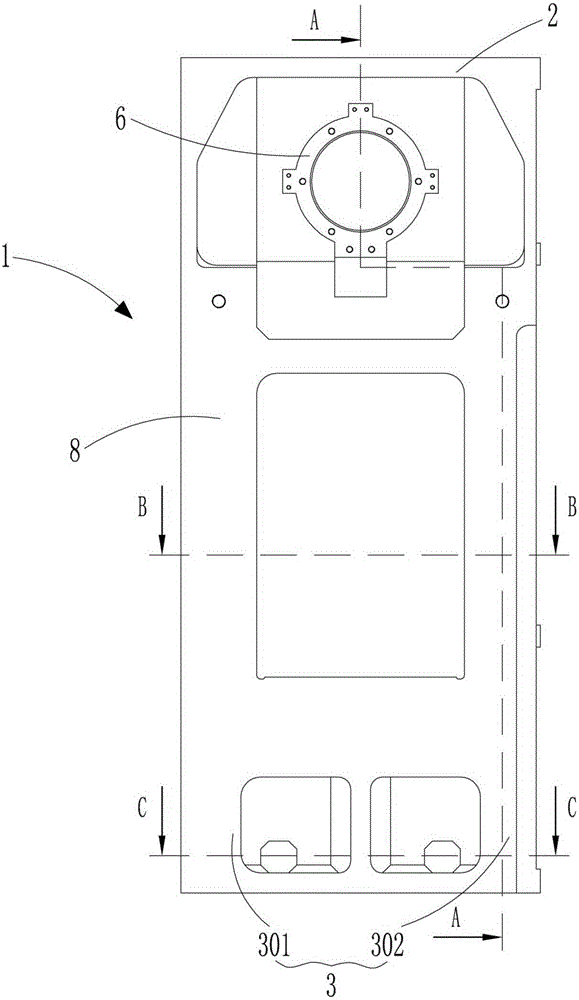
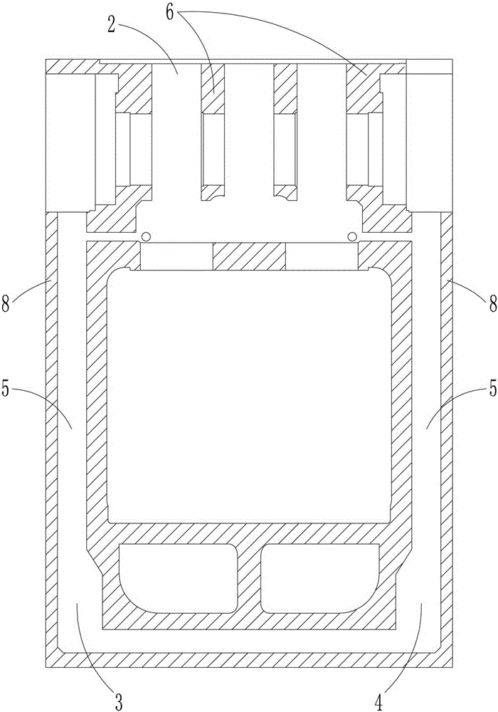
[0020] as attached figure 1 to attach Figure 5 As shown, a one-piece high-speed punch bed, the whole bed is integrally cast, including a main body 1, a crankcase 2 arranged on the main body 1, a main oil tank 3 and an auxiliary oil tank 4 arranged on the main body 1, the main body There are four uprights 8 on 1, and the inner cavity of the uprights 8 forms an oil return pipeline 5 connected between the main oil tank 3 and the crankcase 2, and between the auxiliary oil tank 4 and the crankcase 2, and the crankcase 2 has a bearing seat 6, An oil tank channel 7 connecting the two is arranged between the main oil tank 3 and the auxiliary oil tank 4. The bearing housing 6 includes four crankshaft stamping bearing housings with the same diameter and two crankshaft guide bearing housings with the same diameter. The crankcase 2 is located on ...


PUM


Abstract

The invention discloses an integrated high-speed punch press body. The whole punch press body is integrally cast and comprises a main body, a crank case arranged on the main body, a main oil tank and an auxiliary oil tank, wherein the main oil tank and the auxiliary oil tank are arranged on the main body. The main body is provided with four stand columns, and cavities are formed inside the stand columns to form oil return pipes which communicate the main oil tank and the crank case as well as the auxiliary oil tank and the crank case; a bearing block is arranged inside the crank case; an oil channel which communicates the insides of the main oil tank and the auxiliary oil tank is arranged between the main oil tank and the auxiliary oil tank. Being integrally formed through the casting technology, the whole integrated high-speed punch press body is better in integral rigidity and accordingly solves the influence of assembly errors on precision; the oil return pipe of lubricant oil is integrated inside the integrated punch press body and accordingly is fully sealed without contact with joint guide pipes, further the problem of breakage and oil leakage of the guide pipes can be solved; besides, the thickness of the oil return pipes is larger than the diameter of traditional rubber pipes, so that oil return can be more smooth; the oil tank channel achieves mixing and circulation of the lubricant oil in the main oil tank and the auxiliary oil tank, so that the temperature of every portion of a punch press can be uniform and further thermal deformation can be avoided.

Description

technical field [0001] The invention relates to an integrated high-speed punch bed. Background technique [0002] In the closed gantry press, the general crankshaft bearing housing and the bed are cast separately and processed separately, so the bed is completed through post-assembly. Due to the influence of the assembly process, the bed structure is not compact enough, and the overall rigidity is poor. Due to assembly errors, especially when there are multiple crankshaft bearing seats on a large machine bed, the crankshaft is easily eccentric, and the crankshaft vibration affects the accuracy. [0003] In the high-speed punching machine, each lubricating part uses rubber hoses and joints to guide the lubricating oil back to the oil tank. This oil return method has a complex structure and many plug-in points, which is easy to cause oil leakage and poor oil return. Exposed conduits are also prone to breakage and malfunction. [0004] In the high-speed punching machine, the...

Claims


Application Information

Patent Timeline
Patent Type & Authority Patents(China)
IPC IPC(8): B30B15/04F16N1/00
Inventor 马良费振华吴炯
Owner 苏州欧利锦高速精密冲床科技有限公司
Learn More