Pin feeding system for surface mounting technology (SMT) chip mounter

A feeding system and placement machine technology, applied in the direction of mechanical conveyors, conveying bulk materials, conveyors, etc., can solve the problems of automatic feeding, slow speed, high cost, etc. The effects of batch automatic placement of pins, increased production rate, and improved stability

Active Publication Date: 2014-04-02
深圳市睿勤科技有限公司
View PDF6 Cites 6 Cited by
  • Summary
  • Abstract
  • Description
  • Claims
  • Application Information

AI Technical Summary

Problems solved by technology

The traditional PCB board is to manually insert the steel pins into the corresponding holes of the PCB board. Using this method is not only slow, low output, high cost, but also requires a large number of workers to complete the work, which is a great waste of time. labor resources
At present, there is no SMT placement machine in the market to realize the automation of PCB board pin insertion, mainly because the incoming material of the pins cannot meet the automatic feeding, and the existing feeding system cannot supply materials for the pins, and meet the existing requirements. Retrieval requirements of SMT placement machine

Method used


Image

  • Pin feeding system for surface mounting technology (SMT) chip mounter
  • Pin feeding system for surface mounting technology (SMT) chip mounter
  • Pin feeding system for surface mounting technology (SMT) chip mounter

Examples


Embodiment Construction

[0029] In order to fully understand the technical content of the present invention, the technical solutions of the present invention will be further introduced and illustrated below in conjunction with specific embodiments.

[0030] The concrete structure of the embodiment of the present invention is as Figure 1 to Figure 11 shown.

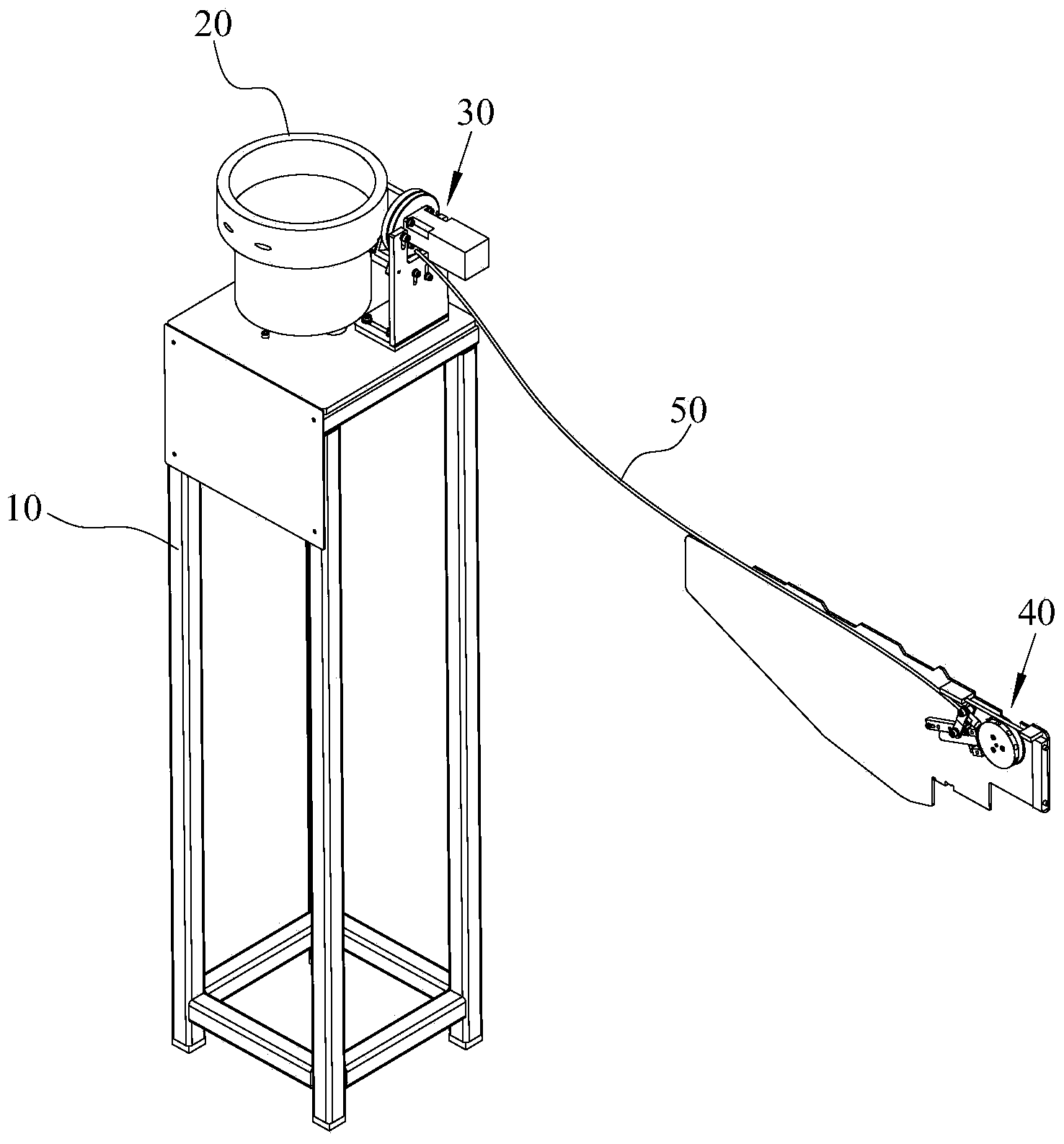
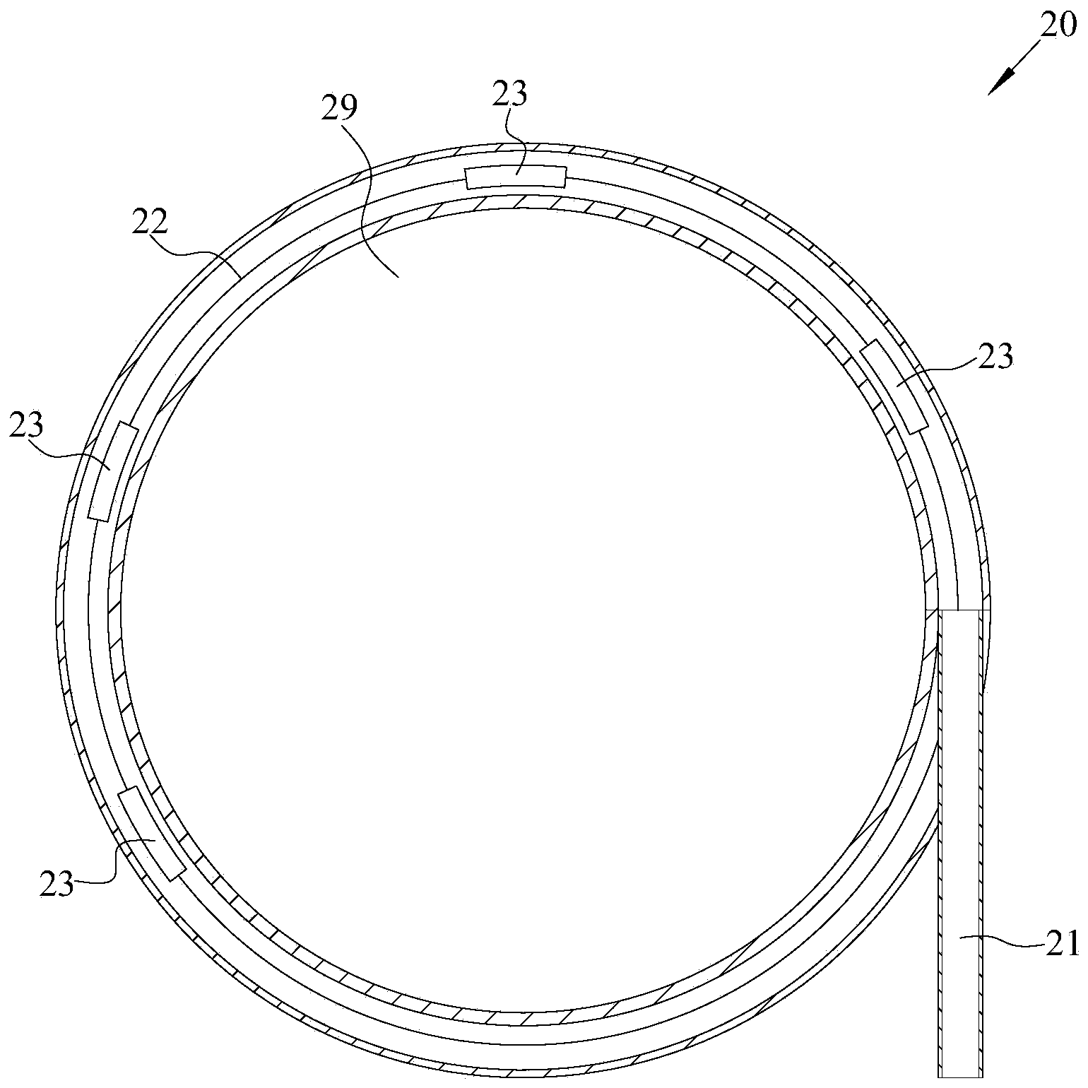
[0031] The pin 60 feeding mechanism includes a main control unit, a workbench 10, a vibrating plate 20 fixed on the workbench 10 for neatly arranging the scattered pins 60, for receiving the pins 60 to wait for the SMT placement machine to insert The material assembly 40 to be removed by the needle 60 and the material transfer assembly 30 for transferring the pin 60 from the vibrating plate 20 to the assembly 40 .

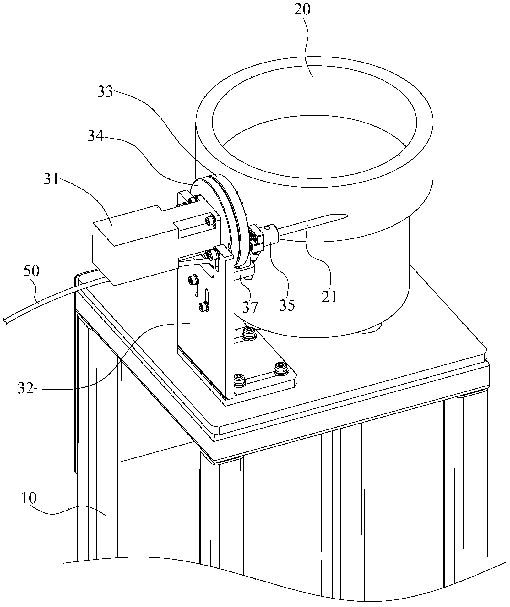
[0032] The concrete structure of material transfer assembly 30 sees Figure 2 to Figure 9 shown. The feeding assembly 30 is fixed on the workbench 10 . The material transfer assembly 30 includes a material storage disc 33, a first...


PUM


Abstract

The invention relates to a pin feeding system for a surface mounting technology (SMT) chip mounter. A material conveying module in the feeding system comprises a storage disc, a first motor and a blowing air port, wherein the first motor is used for driving the storage disc to rotate and electrically connected with a main control unit. The storage disc is provided with storage through holes, the blowing air port corresponds to one storage through hole so as to push pins positioned in the storage through hole to a module which is to take materials through air. According to the feeding system, first the scattered pins are tidied through a vibration disc, the pins are blown through the material conveying module to the module which is to take the materials, finally the SMT chip mounter takes away the pins, full automatic feeding of the scattered pins is achieved through seamless connection of a whole scheme, feeding efficiency and the production rate are effectively improved, full feeding automation of the pins is achieved, the problem that the pins cannot be automatically mounted in large volumes through the SMT chip mounter is solved, and a novel and reliable solution is provided for automatic pin production of an electronic processing industry.

Description

technical field [0001] The invention relates to feeding equipment, in particular to a pin feeding system for an SMT placement machine. Background technique [0002] At present, PCBA manufacturing in the electronics industry continues to develop, requiring a large number of PCB board pin insertion processes. The traditional PCB board is to manually insert the steel pins into the corresponding holes of the PCB board. Using this method is not only slow, low output, high cost, but also requires a large number of workers to complete the work, which is a great waste of time. labor resources. At present, there is no SMT placement machine in the market to realize the automation of PCB board pin insertion, mainly because the incoming material of the pins cannot meet the automatic feeding, and the existing feeding system cannot supply materials for the pins, and meet the existing requirements. Retrieval requirements for SMT placement machines. Contents of the invention [0003] T...

Claims


Application Information

Patent Timeline
Patent Type & Authority Applications(China)
IPC IPC(8): B65G37/00B65G47/52B65G47/256B65G47/28B65G53/06B65G53/34B65G29/00
Inventor 鲁宁张宁
Owner 深圳市睿勤科技有限公司
Why Eureka
Try Eureka