Driver with hydraulic tappet

A technology of hydraulic tappets and drives, which is applied in the direction of engine components, machines/engines, mechanical equipment, etc., can solve problems such as noise life, achieve reasonable life, optimize hydraulic tappet design, and reduce noise

Inactive Publication Date: 2014-04-02
NINGBO HOYEA MACHINERY MFG
View PDF5 Cites 13 Cited by
  • Summary
  • Abstract
  • Description
  • Claims
  • Application Information

AI Technical Summary

Problems solved by technology

If the gap is too large, it will c...

Method used


Image

  • Driver with hydraulic tappet
  • Driver with hydraulic tappet

Examples


Embodiment Construction

[0060] The following will clearly and completely describe the technical solutions in the embodiments of the present invention. Obviously, the described embodiments are only some of the embodiments of the present invention, rather than all the embodiments. Based on the embodiments of the present invention, all other embodiments obtained by persons of ordinary skill in the art without making creative efforts belong to the protection scope of the present invention.

[0061] in this manual the term" Top" and " Bottom" or " on" and " "Down" and other orientation terms are only used to indicate the relative positions of the various parts of the driver in the figure, and do not limit the installation position or direction of the driver itself with hydraulic tappets.

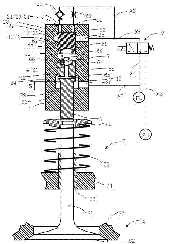
[0062] Such as figure 1 As shown, the driver with hydraulic tappet in the first preferred embodiment of the present invention includes a driver housing 1 . In the driver housing 1, a drive cylinder 2, a first pist...


PUM


Abstract

The invention discloses a driver with a hydraulic tappet. The driver comprises a driver shell, a driving cylinder, a first piston, a second piston, a piston rod and the hydraulic tappet, wherein the hydraulic tappet further comprises a tappet plunger, a tappet body, a tappet high-pressure chamber, a tappet inflow channel, a discharge channel, a tappet one-way valve and a plunger return spring. The hydraulic tappet is optimized in design, and the driver with the hydraulic tappet has comprehensive advantages in terms of spatial size, high-pressure chamber pressure and cost, and is particularly applicable to valve clearance control of a variable valve driver. The hydraulic tappet is combined among the wall of the driving cylinder and the two pistons of the driver, the tappet body includes a tappet body end and a tappet body wall, the first piston serves as the tappet body end, the wall of the driving cylinder serves as the tappet body wall, so that the tappet high-pressure chamber can have a diameter as large as that of the driving cylinder to reduce the internal high pressure of the tappet high-pressure chamber, a normal air distribution function, low noise and reasonable service life are ensured, an additional tappet body wall structure and an additional high-precision matching structure are omitted, and manufacturing cost is reduced.

Description

technical field [0001] The present invention relates to a control technology of a driving machine, and in particular relates to a driver with a hydraulic tappet, which is especially suitable for a variable valve drive of an engine, where the valve can be the traditional intake valve and The exhaust valve can also be a device specially used to control gaseous fuel. Background technique [0002] Various variable valve systems are being used and developed to effectively control valve timing and lift to improve engine performance, fuel economy, injection and other characteristics. These systems can mainly be classified into mechanical, electrohydraulic and electromagnetic forms according to the devices or drives controlled. According to the scope of control, it can be divided into variable valve lift and timing, variable valve timing and variable valve lift. They can also be divided into cam-based and camless forms. The design of these variable valve systems also needs to con...

Claims


Application Information

Patent Timeline
IPC IPC(8): F01L1/245
Inventor 娄征
Owner NINGBO HOYEA MACHINERY MFG
Why Eureka
Try Eureka