
Self-ballast LED (Light Emitting Diode) spot lamp

A LED spotlight and self-ballasting technology, which is applied in lighting devices, cooling/heating devices of lighting devices, light sources, etc., can solve the problems of complex production and assembly structure, large volume, and low production efficiency, and achieve light weight and volume Small, easy-to-assemble effect

Inactive Publication Date: 2014-04-02
深圳市亮百佳电子科技有限公司
View PDF5 Cites 3 Cited by
  • Summary
  • Abstract
  • Description
  • Claims
  • Application Information

AI Technical Summary

Problems solved by technology

At present, the commonly used LED lighting devices are LED bulb lamps and LED spotlights. In the prior art, for the application of LED lighting technology, the problem of heat dissipation still needs to be solved urgently. In high-power LED lighting devices, passive heat dissipation It often cannot meet the heat dissipation requirements. It is usually designed as an active heat dissipation technology, that is, the design of the high thermal conductivity aluminum profile lamp body structure is the main heat sink, and the high thermal conductivity silicone grease is filled between the lamp body and the light source to closely cooperate, and the heat of the light source is quickly transmitted through the lamp body. Outside the lamp body, it uses a built-in fan to carry out forced air circulation to dissipate heat. Although the heat dissipation effect is good, the product is generally large in size, which usually cannot meet people's pursuit of miniaturization, and its production and assembly structure is complex and the production efficiency is low.

Method used


Image

  • Self-ballast LED (Light Emitting Diode) spot lamp
  • Self-ballast LED (Light Emitting Diode) spot lamp
  • Self-ballast LED (Light Emitting Diode) spot lamp

Examples


Embodiment Construction

[0023] This embodiment is a preferred implementation mode of the present invention, and other principles and basic structures that are the same or similar to this embodiment are within the protection scope of the present invention.

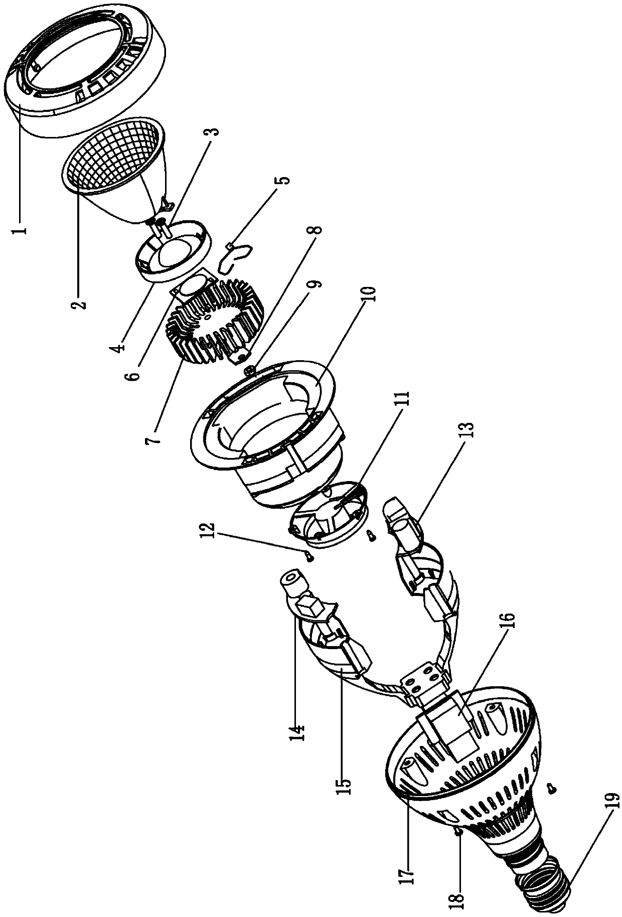
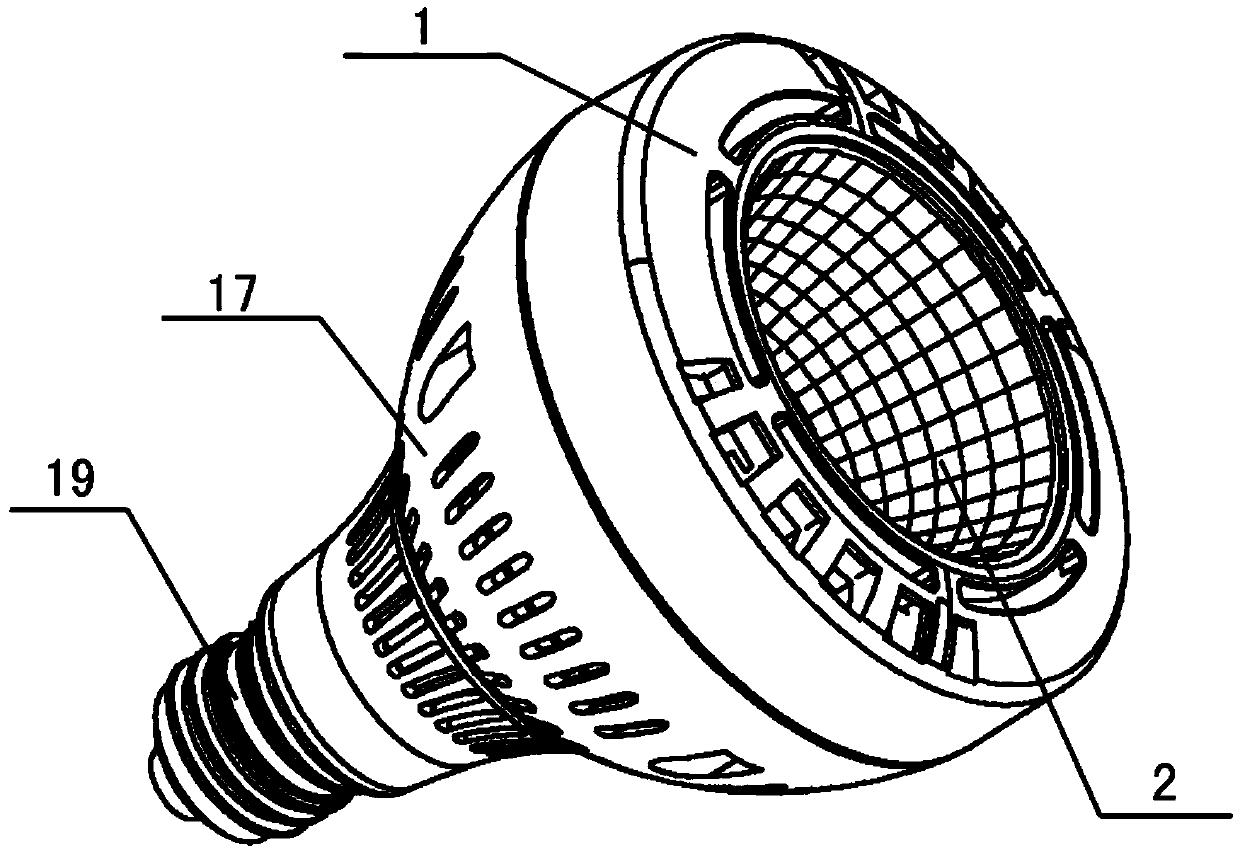
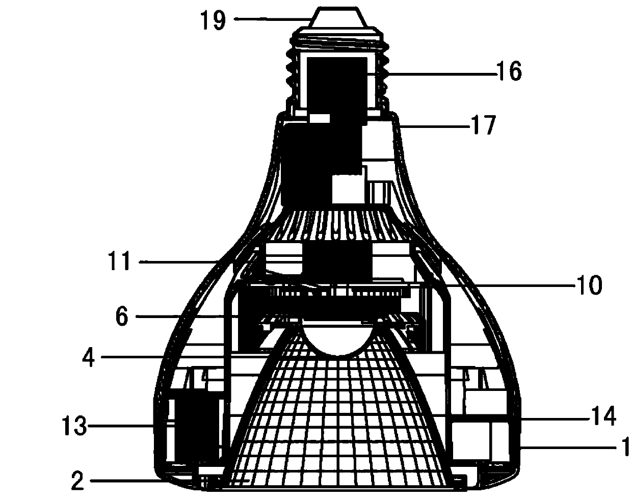
[0024] Please refer to the attached figure 1 to attach Figure 5 , the present invention mainly includes a lamp holder 19, an adapter 17, an air distribution cover 10, a power supply device 13, 14, 16, a fan 11, a lamp body 7, a light source 6, a light source fixing seat 4, a reflector cup 2 and a cover 1, and the lamp holder 19 It is fixedly installed at the rear end of the adapter 17. In this embodiment, the lamp cap 19 adopts an E27 interface lamp cap. During specific implementation, lamp caps of other interface forms can also be used according to actual needs. The power supply device is installed in the adapter 17. In this embodiment, the power supply device has a saddle shape as a whole, or it can also be defined as a "U" shape. The bottom o...


PUM


Abstract

The invention relates to a self-ballast LED (Light Emitting Diode) spot lamp. The LED spot lamp comprises a lamp head, an adapter, an air distribution hood, a power supply device, a fan, a lamp body, a light source, a reflection cup and a surface cover, wherein the lamp head is fixedly arranged at the rear end of the adapter; the power supply device is arranged inside the adapter; the air distribution hood is integrally convex, the main body of the air distribution hood is cylindrical, the top of the air distribution hood is provided with an edge overturning outwards, and an air inlet port is formed in the edge; the air distribution hood is fixedly arranged inside the adapter; the fan is fixedly arranged at the bottom of the air distribution hood; the lamp body is fixedly arranged at the bottom of the inner side of the air distribution hood; the light source is attached in the lamp body; the reflection cup is arranged above the light source; the surface cover is arranged above the reflection cup; the reflection cup is fixedly arranged inside the air distribution hood through the surface cover. A magnetic suspension fan is arranged on an aluminum radiator, and a wind deflector device is designed for matching with the fan to form a good wind inlet and outlet radiating loop and exhaust the internal heat of the lamp, thus the difficulty of heat radiation of an LED lamp is solved, and an energy-saving LED lamp with high power of 30W and high light efficiency is realized.

Description

technical field [0001] The invention discloses an LED spotlight, in particular to a self-ballasted LED spotlight. Background technique [0002] With the continuous maturity and development of LED lighting technology, LED lighting is more and more widely used in people's daily life. At present, the commonly used LED lighting devices are LED bulb lamps and LED spotlights. In the prior art, for the application of LED lighting technology, the problem of heat dissipation still needs to be solved urgently. In high-power LED lighting devices, passive heat dissipation It often cannot meet the heat dissipation requirements. It is usually designed as an active heat dissipation technology, that is, the design of the high thermal conductivity aluminum profile lamp body structure is the main heat sink, and the high thermal conductivity silicone grease is filled between the lamp body and the light source to closely cooperate, and the heat of the light source is quickly transmitted through...

Claims


Application Information

Patent Timeline
IPC IPC(8): F21S2/00F21V29/02F21Y101/02F21K9/233F21K9/235F21K9/238F21V29/67F21V29/74F21Y115/10
Inventor 颜小民
Owner 深圳市亮百佳电子科技有限公司
Learn More