
Pre-mixing and pre-evaporation low-pollution combustion chamber with double-oil-way four-rotational-flow pre-film type main combustion stage

A technology of pre-membrane main and main combustion stages, applied in combustion chambers, continuous combustion chambers, combustion methods, etc., to achieve uniform combustion, reduced pollution emissions, and reduced pollution emissions

Active Publication Date: 2014-04-02
BEIHANG UNIV +1
View PDF20 Cites 13 Cited by
  • Summary
  • Abstract
  • Description
  • Claims
  • Application Information

AI Technical Summary

Problems solved by technology

[0022] The technical problem to be solved by the present invention is: to overcome the deficiencies of the existing technology, and to use the premixed pre-evaporation combustion technology to provide a premixed pre-evaporation low-pollution combustion chamber with dual oil channels and four-swirling flow pre-film main combustion stages. The chamber adopts the mode of central staged combustion, the pre-combustion stage is in the center, and the combination of diffusion combustion and premixed combustion is adopted to ensure the stability and safety of the combustion chamber and reduce pollution emissions under small working conditions; the main The combustion stage adopts the premixed pre-evaporation combustion method, which can effectively reduce combustion pollutants

Method used


Image

  • Pre-mixing and pre-evaporation low-pollution combustion chamber with double-oil-way four-rotational-flow pre-film type main combustion stage
  • Pre-mixing and pre-evaporation low-pollution combustion chamber with double-oil-way four-rotational-flow pre-film type main combustion stage
  • Pre-mixing and pre-evaporation low-pollution combustion chamber with double-oil-way four-rotational-flow pre-film type main combustion stage

Examples


Embodiment Construction

[0044] The present invention will be further described below with reference to the accompanying drawings and specific embodiments.

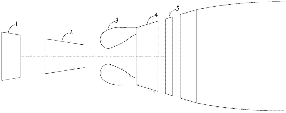
[0045]figure 1 It is a schematic diagram of the engine structure, including a low-pressure compressor 1, a high-pressure compressor 2, a combustion chamber 3, a high-pressure turbine 4 and a low-pressure turbine 5. When the engine is working, the air is compressed by the low-pressure compressor 1, and then enters the high-pressure compressor 2. The high-pressure air enters the combustion chamber 3 and burns with the fuel oil. The high-temperature and high-pressure gas formed after combustion enters the high-pressure turbine 4 and the low-pressure turbine 5. The work drives the high pressure compressor 2 and the low pressure compressor 1 respectively.

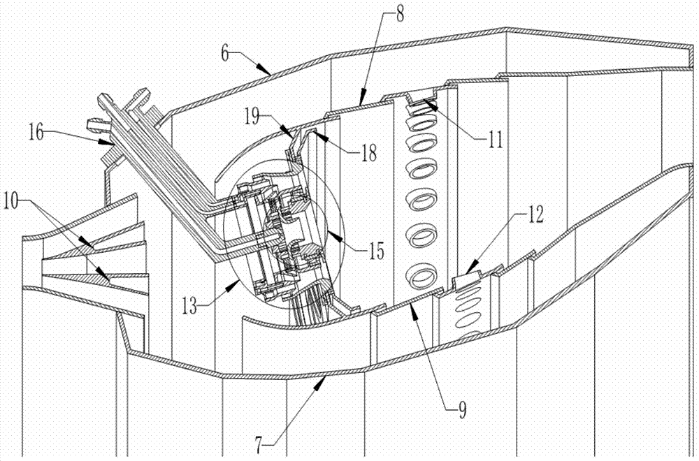
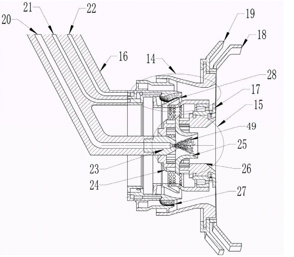
[0046] like figure 2 As shown, the head of the combustion chamber adopts a central grading structure, the pre-combustion stage is in the center, and the main combustion stage is in the radial per...


PUM


Abstract

The invention relates to a pre-mixing and pre-evaporation low-pollution combustion chamber with a double-oil-way four-rotational-flow pre-film type main combustion stage. The combustion chamber is of a single-ring-cavity structure, and adopts a central staged combustion mode, wherein the head of the combustion chamber is divided into a preliminary combustion stage and a main combustion stage, the preliminary combustion stage adopts a mode of combining diffusive combustion with rotational-flow pre-mixing combustion, and is capable of reducing pollutant discharge under low-flow working conditions while ensuring combustion stability; the main combustion stage adopts a mode of pre-mixing and pre-evaporation combustion, and is capable of effectively reducing combustion pollutants. The oil way of the main combustion stage is divided into two stages, fuel oil in each stage forms an oil film on a pre-film plate, and the oil films are atomized, evaporated and blended under the action of two rotational flows to form a uniform oil-gas mixture, thus facilitating reduction for the combustion pollutants; due to the double-oil-way design, the one-stage working of the main combustion stage under low-flow and medium-flow working conditions such as entrance, and the two-stage working of the main combustion stage under high-flow working conditions such as take-off can be met, thus facilitating the oil-gas matching of the combustion chamber under different working conditions, and further reducing the pollutant discharge level of the whole landing and take-off circulation of the combustion chamber of an aeroengine.

Description

technical field [0001] The invention relates to the technical field of aviation gas turbines, in particular to a premixed preevaporation low-polluting combustion chamber with dual oil circuits and four swirl pre-film main combustion stages. , using the combination of diffusion combustion and premixed combustion to ensure the stability and safety of the combustion chamber, while reducing pollution emissions under small working conditions; the main combustion stage of the dual oil circuit is at the radial periphery of the pre-combustion stage, Using the method of premixing and preevaporating combustion, the design of the dual oil circuits of the main combustion stage can meet the requirements of the main combustion stage to work in the first stage under small and medium operating conditions such as approaching, and the main combustion stage in the large operating conditions such as takeoff. It is conducive to the matching of oil and gas in the combustion chamber under different ...

Claims


Application Information

Patent Timeline
Patent Type & Authority Applications(China)
IPC IPC(8): F23R3/52F23R3/58F23R3/32F23R3/38
Inventor 林宇震李林张弛康尧
Owner BEIHANG UNIV
Learn More