Prop drawing-shaped micro-mechanical solid fluctuating modal matching gyroscope

A technology of micro-mechanics and drive mode, which is applied in gyroscope/steering sensing equipment, measuring devices, surveying and mapping and navigation, etc. It can solve the problems of limited application, inconvenient detection accuracy, and large gyroscope bandwidth, so as to reduce temperature sensitivity , Facilitate mass production and improve sensitivity

Active Publication Date: 2014-04-02
SHANGHAI JIAO TONG UNIV
View PDF4 Cites 1 Cited by
  • Summary
  • Abstract
  • Description
  • Claims
  • Application Information

AI Technical Summary

Problems solved by technology

[0005] This technology has the following disadvantages: the structure of the micro-gyro resonator of the spring mass system is fragile, which limits its application in many shock-resistant conditions; the processing technology of the gyro is relatively complicated, the processing cost is high, and it is not suitable for mass production; The frequency split between the gyro drive mode and the detection mode is large, resulting in a large bandwidth of the gyro, and it is difficult to improve the quality factor; the noise of the gyro is large, and the generated signal is small, which is not easy to improve the accuracy of detection

Method used


Image

  • Prop drawing-shaped micro-mechanical solid fluctuating modal matching gyroscope
  • Prop drawing-shaped micro-mechanical solid fluctuating modal matching gyroscope
  • Prop drawing-shaped micro-mechanical solid fluctuating modal matching gyroscope

Examples


Embodiment Construction

[0035] The present invention will be described in detail below in conjunction with specific embodiments. The following examples will help those skilled in the art to further understand the present invention, but do not limit the present invention in any form. It should be pointed out that for those of ordinary skill in the art, a number of modifications and improvements can be made without departing from the concept of the present invention. These all belong to the protection scope of the present invention.

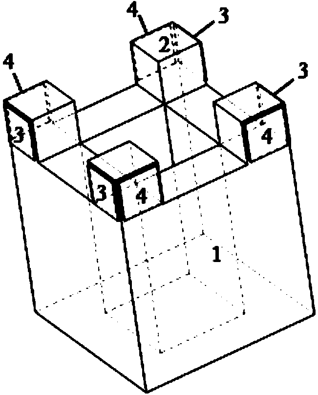
[0036] Such as figure 1 As shown, the first embodiment provides a cylindrical micromachined solid wave mode matching gyroscope, including:

[0037] One cylindrical resonator 1;

[0038] Four cube protrusions 2 at the top four corners of the cylindrical resonator 1;

[0039] Four contact metal driving electrodes 3 arranged along the cube protrusions 2;

[0040] Four contact metal detection electrodes 4 arranged along the cube protrusions 2.

[0041] In this embodiment, the materia...


PUM


Abstract

The invention provides a prop drawing-shaped micro-mechanical solid fluctuating modal matching gyroscope which comprises a prop drawing-shaped harmonic oscillator with four cube bulges at the four corners of the top end, four driving electrodes which are distributed above or nearby the cube bulges on the top end of the harmonic oscillator along the side face of the harmonic oscillator, and four detecting electrodes which are distributed above or nearby the cube bulges on the top end of the harmonic oscillator along the side face of the harmonic oscillator, wherein the spatial positions of the four driving electrodes are perpendicular to those of the four detecting electrodes. The gyroscope works by the means that the driving modality and the detecting modality of the prop drawing-shaped harmonic oscillator are matched with each other; the alternating voltage is applied onto the two driving electrodes on the prop drawing-shaped harmonic oscillator, and the inverse piezoelectric effect or the capacitive sensing effect enables the prop drawing-shaped harmonic oscillator to vibrate under the driving modality; in the case that an input angular velocity exists, the vibration model of the prop drawing-shaped harmonic oscillator is converted into the detecting modality, and sensitive signals generated by the piezoelectric positive effect or the capacitive sensing effect of the detecting electrodes are processed by a peripheral circuit to obtain input angular velocity signals.

Description

Technical field [0001] The invention relates to a solid wave mode matching gyroscope in the field of micro-electromechanical technology, and in particular to a cylindrical micro-machined solid wave mode matching gyroscope. Background technique [0002] A gyroscope is an inertial device that can be sensitive to the angle or angular velocity of the carrier. It plays a very important role in the fields of attitude control and navigation and positioning. With the development of national defense technology and aviation and aerospace industries, the requirements of inertial navigation systems for gyroscopes are also developing in the direction of low cost, small size, high precision, multi-axis detection, high reliability, and adaptability to various harsh environments. Micro-gyros based on MEMS technology are processed by micro-nano batch manufacturing technology, and their cost, size, and power consumption are very low, and environmental adaptability, working life, reliability, and i...

Claims


Application Information

Patent Timeline
Patent Type & Authority Applications(China)
IPC IPC(8): G01C19/56
CPCG01C19/5747
Inventor 张卫平汪濙海刘亚东成宇翔唐健张弓许仲兴孙殿竣陈文元
Owner SHANGHAI JIAO TONG UNIV
Why Eureka
Try Eureka