Micro-cavity interference flow velocity differential-pressure-sensitive structure and flow velocity and quantity sensor with micro-cavity interference fiber

A technology of flow sensor and sensitive structure, which is applied in the direction of fluid velocity measurement, velocity/acceleration/shock measurement, flow/mass flow measurement, etc. It can solve the problems of measurement sensitivity drop, influence of measurement accuracy, polarization signal fading, etc., and achieve the elimination of polarization Signal fading, high measurement sensitivity, and the effect of eliminating interference

Inactive Publication Date: 2014-04-02
UNIV OF ELECTRONIC SCI & TECH OF CHINA
View PDF6 Cites 12 Cited by
  • Summary
  • Abstract
  • Description
  • Claims
  • Application Information

AI Technical Summary

Problems solved by technology

However, the interference optical path of the traditional fiber optic interferometer is very long, and there will inevitably be serious polarization signal fading and signal temperature drift, which will affect the measurement accuracy; at the same tim

Method used


Image

  • Micro-cavity interference flow velocity differential-pressure-sensitive structure and flow velocity and quantity sensor with micro-cavity interference fiber
  • Micro-cavity interference flow velocity differential-pressure-sensitive structure and flow velocity and quantity sensor with micro-cavity interference fiber
  • Micro-cavity interference flow velocity differential-pressure-sensitive structure and flow velocity and quantity sensor with micro-cavity interference fiber

Examples


Embodiment 1

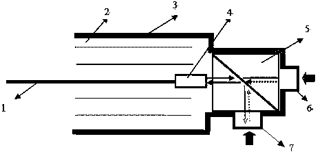
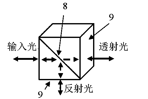
[0051] The microcavity interference flow rate pressure difference sensitive structure of this embodiment includes a transmission optical fiber, a housing, an optical fiber collimator disposed in the housing, and a light beam splitting cube; the light beam splitting cube is connected to and sleeved on the housing The first pressure-sensitive diaphragm for sensing hydrostatic pressure and the second pressure-sensitive diaphragm for sensing fluid velocity pressure; the optical fiber collimator collimates the light wave signal in the transmission fiber and outputs it to the optical beam splitting cube , and the interference light wave signal generated by the reflection of the first and second pressure-sensitive diaphragms is coupled into the transmission fiber; The reflected light of the sensitive diaphragm interferes to form an interference light wave signal carrying flow velocity and pressure difference information.

Embodiment 2

[0053] The microcavity interference flow rate pressure difference sensitive structure of this embodiment includes a transmission optical fiber, a housing, an optical fiber collimator disposed in the housing, and a light beam splitting cube; the light beam splitting cube is connected to and sleeved on the housing The first pressure-sensitive diaphragm for sensing hydrostatic pressure and the second pressure-sensitive diaphragm for sensing fluid velocity pressure; the optical fiber collimator collimates the light wave signal in the transmission fiber and outputs it to the optical beam splitting cube , and the interference light wave signal generated by the reflection of the first and second pressure-sensitive diaphragms is coupled into the transmission fiber; The reflected light of the sensitive diaphragm interferes to form an interference light wave signal carrying flow velocity and pressure difference information; the housing is filled with packaging filling materials for stabl...

Embodiment 3

[0055]The microcavity interference flow velocity and pressure difference sensitive structure of this embodiment includes a transmission optical fiber, a housing, a self-focusing lens arranged in the housing, and a light beam splitting cube; the light beam splitting cube is connected to and sleeved on the housing. The first pressure-sensitive diaphragm for sensing hydrostatic pressure and the second pressure-sensitive diaphragm for sensing fluid velocity pressure; the self-focusing lens collimates the light wave signal in the transmission fiber and outputs it to the light beam splitting cube, And the interference light wave signal generated by reflecting back the first and second pressure-sensitive diaphragms is coupled into the transmission fiber; the light beam splitting cube divides the output light of the self-focusing lens into two beams, and makes the first and second pressure-sensitive diaphragms The reflected light of the sheet interferes to form an interference light wa...


PUM


Abstract

The invention discloses a micro-cavity interference flow velocity differential-pressure-sensitive structure and a flow velocity and quantity sensor with a micro-cavity interference fiber. By the aid of the micro-cavity interference flow velocity differential-pressure-sensitive structure and the flow velocity and quantity sensor, problems of extremely long interference light paths, severe polarization signal fading and temperature drifting of signals and influence on the measurement precision of existing fiber-optic interferometers can be solved. The micro-cavity interference flow velocity differential-pressure-sensitive structure comprises a transmission fiber, a shell, a fiber collimator and a light beam splitting cube; the fiber collimator and the light beam splitting cube are arranged in the shell; the light beam splitting cube is connected with a first pressure-sensitive membrane and a second pressure-sensitive membrane which are sleeved on the shell, the first pressure-sensitive membrane is used for sensing the static pressure of liquid, and the second pressure-sensitive membrane is used for sensing the flow velocity pressure of the liquid; light-wave signals in the transmission fiber are collimated by the fiber collimator and are outputted to the light beam splitting cube, and interference light-wave signals which are reflected by the first pressure-sensitive membrane and the second pressure-sensitive membrane are coupled by the fiber collimator and are inputted into the transmission fiber; light outputted by the fiber collimator is split into two beams by the light beam splitting cube, and light reflected by the first pressure-sensitive membrane is interfered with and light reflected by the second pressure-sensitive membrane by the aid of the light beam splitting cube, so that the interference light-wave signals with flow velocity differential pressure information can be generated.

Description

technical field [0001] The invention belongs to the technical field of optical fiber sensing, and in particular relates to a microcavity interference flow velocity differential sensitive structure for obtaining fluid velocity differential pressure light wave phase modulation information and a microcavity interference optical fiber velocity flow sensor for measuring fluid velocity and flow rate. Background technique [0002] The flow rate and flow rate of fluid are one of the most important monitoring parameters in the field of modern industrial control. There are many technologies and methods to realize fluid flow rate measurement (flow rate is usually realized by flow rate measurement), such as electronic flow rate flowmeter. However, for many special fluid velocity / flow measurements, such as crude oil flow testing of high-temperature and high-pressure oil wells, conventional electronic measuring instruments are limited by temperature limitations, electromagnetic interferen...

Claims


Application Information

Patent Timeline
IPC IPC(8): G01F1/66G01P5/26
Inventor 代志勇
Owner UNIV OF ELECTRONIC SCI & TECH OF CHINA
Why Eureka
Try Eureka