A box-type heat preservation/radiation device for blade servers

A blade server and heat dissipation device technology, which is applied in cooling/ventilation/heating transformation, instruments, electrical digital data processing, etc., can solve the problems that storage devices are not suitable for low-temperature operation, poor heat dissipation effect, and difficult implementation, and achieve separation Simple and reliable fastening, simple and compact structure, and improved heat dissipation efficiency

Active Publication Date: 2018-05-25
NO 709 RES INST OF CHINA SHIPBUILDING IND CORP
View PDF5 Cites 1 Cited by
  • Summary
  • Abstract
  • Description
  • Claims
  • Application Information

AI Technical Summary

Problems solved by technology

Commercial servers usually use forced air cooling through the front and back, but this method cannot be used in harsh environments. When the environmental conditions are humid or contain corrosive substances such as mold and salt spray, a closed structure must be used to separate the circuit board from the harsh environment. Environmental isolation, but this makes heat dissipation difficult
In this case, in order to obtain a good heat dissipation effect, when the power dissipation of the equipment is too large, the industry usually considers the use of water cooling to solve the heat dissipation problem, but the water cooling method is limited by external conditions, such as: there must be a water source If you use self-circulating water, you have to bring your own water tank pump, water pipeline, cooling device, etc. For some small and medium-sized servers, it is difficult to implement
Moreover, there is a hidden danger of water leakage in water cooling, and its safety needs to be considered
[0003] In addition, the storage device in the server is not suitable for low temperature operation, so preheating measures are required, but heating and heat dissipation are often contradictory, because usually good heat preservation effect means poor heat dissipation effect

Method used


Image

  • A box-type heat preservation/radiation device for blade servers
  • A box-type heat preservation/radiation device for blade servers
  • A box-type heat preservation/radiation device for blade servers

Examples


Embodiment Construction

[0022] Below in conjunction with accompanying drawing, the present invention is described in further detail:

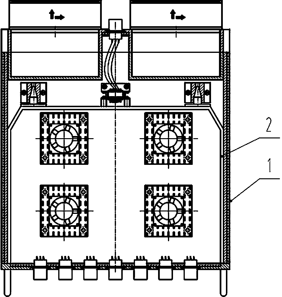
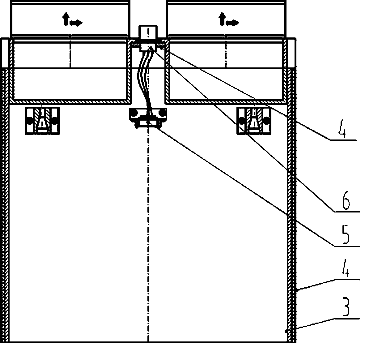
[0023] like Figure 1 to Figure 6 As shown, the present invention is a box-type heat preservation / radiation device for blade servers, which is composed of an outer box 1 and an inner box 2, and the inner box 2 and the outer box 1 are guided by a conical guide at the tail of the inner box Locating pin 16 and the screw on inner case front panel 13 are fixed.

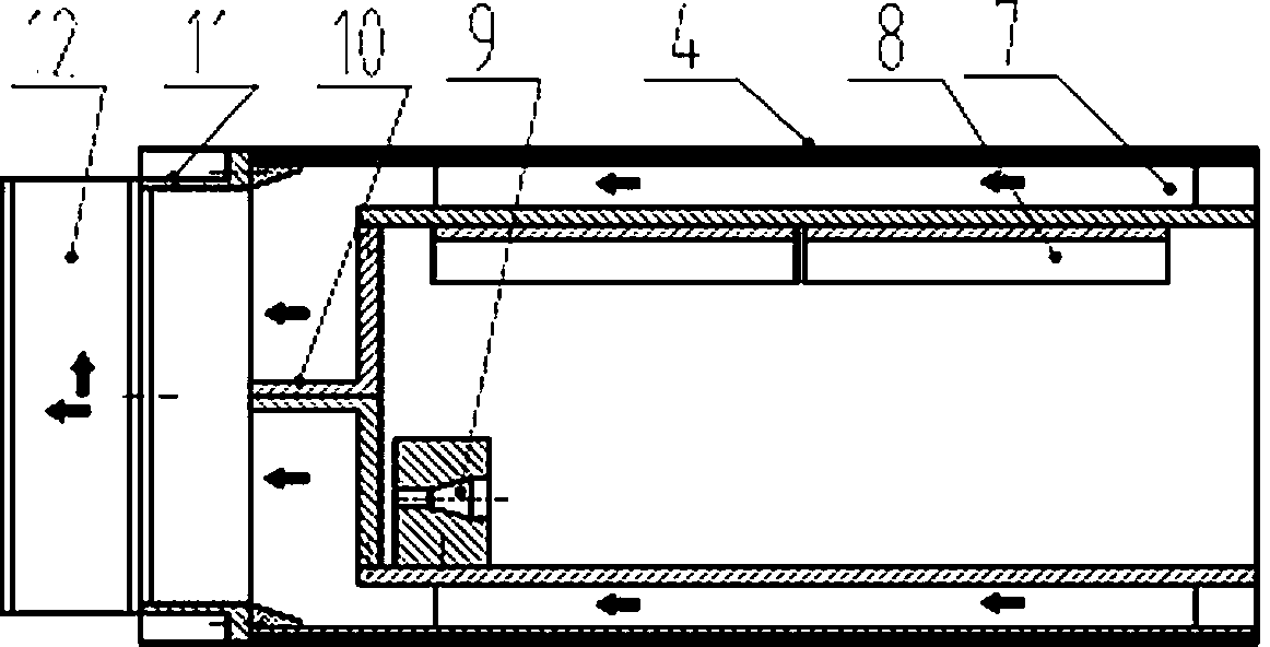
[0024] The outer box 1 is a thermal insulation / radiation box body, including: side panels 3, heat insulation panels 4, colliding adapter sockets 5, external connectors 6, air duct panels 7, fin radiators 8, conical Positioning pin seat 9, induced air box 10, confluence air box 11, external fan 12; the upper and lower sides of outer box 1 are composed of air duct plate 7 and heat insulation plate 4, air duct plate 7 is on the inside, and heat insulation plate 4 is on the outside ; On the inner side of the upper a...


PUM


Abstract

A box-type heat preservation / radiation device for blade servers adopts the structure of an inner and outer box, the inner box is a carrying box for electrical components, and the outer box is a heat preservation / radiation box. The upper and lower planes of the outer box of the device are air duct insulation / heat transfer surfaces, and the rest are heat insulation surfaces. The heat dissipation and heat preservation of the chassis are controlled by controlling the on-off of the air flow in the upper and lower heat transfer air ducts. Mounting the finished radiator increases the heating surface of the outer box to improve heat dissipation efficiency; the heating chip in the inner box adopts a dual-path heat transfer method of upward convection and downward conduction to reduce heat flux density and improve heat transfer efficiency; The clutch of the tapered pin hole realizes separation and fastening. The device uses economical and safe natural air as the heat transfer medium, and realizes safe, energy-saving and compact heat preservation / radiation functions through structural design without relying on refrigeration facilities.

Description

technical field [0001] The invention relates to the technical field of electronic heat dissipation, in particular to a box-type heat preservation / radiation device for blade servers. Background technique [0002] The blade server is characterized by a large planar size and a small thickness. Since the blade server has powerful data processing and storage capabilities, its heat consumption is correspondingly large. Commercial servers usually use forced air cooling through the front and back, but this method cannot be used in harsh environments. When the environmental conditions are humid or contain corrosive substances such as mold and salt spray, a closed structure must be used to separate the circuit board from the harsh environment. Environmental isolation, but this makes heat dissipation difficult. In this case, in order to obtain a good heat dissipation effect, when the power dissipation of the equipment is too large, the industry usually considers the use of water cooli...

Claims


Application Information

Patent Timeline
Patent Type & Authority Patents(China)
IPC IPC(8): G06F1/20H05K7/20
CPCY02D10/00
Inventor 严红陈艳华
Owner NO 709 RES INST OF CHINA SHIPBUILDING IND CORP
Why Eureka
Try Eureka