Wideband sound absorption structure combing mechanical impedance of composite resonance cavities with micropunch plates

A mechanical impedance, micro-perforated plate technology, applied in the direction of sound-producing instruments, instruments, etc., can solve the problems of poor high-frequency sound absorption, complex structure, occupying a large space, etc., and achieve the effect of sound absorption frequency bandwidth

Inactive Publication Date: 2014-04-02
JIANGSU UNIV
View PDF9 Cites 21 Cited by
  • Summary
  • Abstract
  • Description
  • Claims
  • Application Information

AI Technical Summary

Problems solved by technology

The high sound absorption coefficient of the micro-perforated plate structure occurs near the cavity resonance, and the structural resonance frequency is mainly determined by the thickness of the back cavity. In order to obtain a good low-frequency sound absorption effect, the micro-perforated plate structure must be made very thick and occupy A large amount of space will encounter difficulties in actual engineering, so the low-frequency sound absorption performance of micro-perforated panels is not good, which has become a bottleneck restricting its engineering application
[0003] At present, in order to improve the low-frequency sound absorption performance of the sound-absorbing structure, some scholars have designed a composite structure that combines micro-perforated panels with sound-absorbing materials, but after using sound-absorbing materials, the structure has the disadvantage of secondary pollution, even so , in order to absorb sound well at low frequencies, the thicknes

Method used


Image

  • Wideband sound absorption structure combing mechanical impedance of composite resonance cavities with micropunch plates
  • Wideband sound absorption structure combing mechanical impedance of composite resonance cavities with micropunch plates
  • Wideband sound absorption structure combing mechanical impedance of composite resonance cavities with micropunch plates

Examples


Embodiment Construction

[0017] specific implementation plan

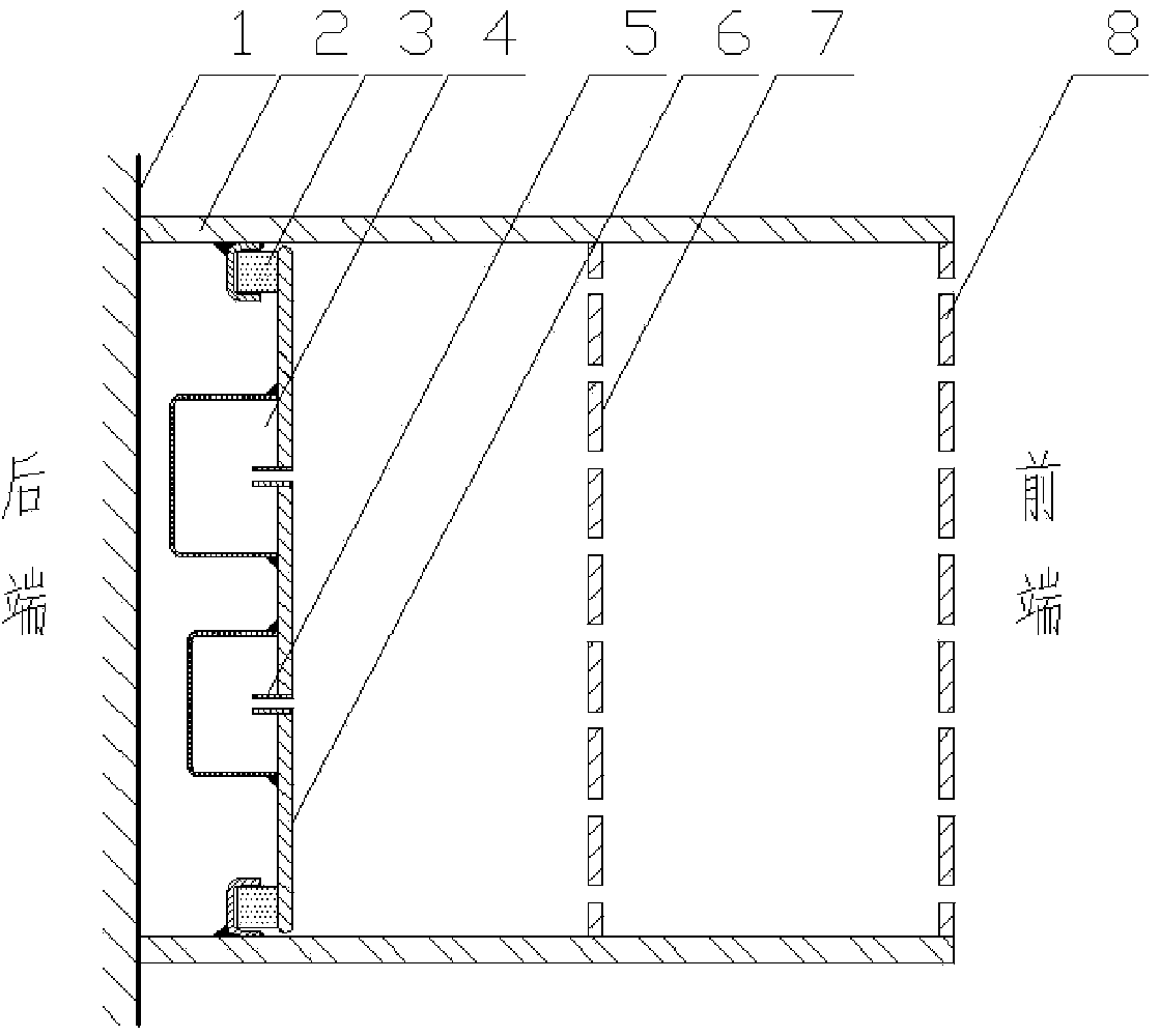
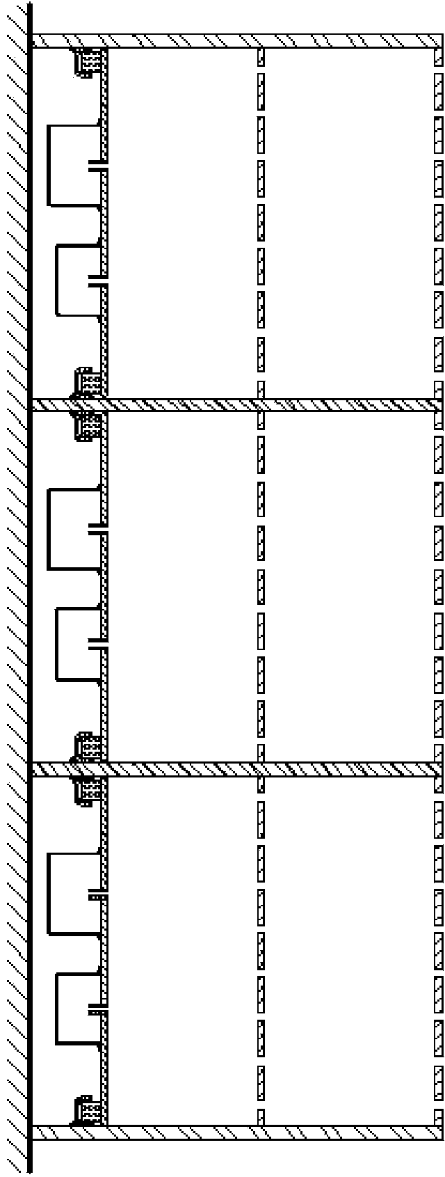
[0018] combined with figure 1 And attached figure 2 The implementation method of the present invention will be described.

[0019] attached figure 1 It is the basic structural diagram of the present invention. The bracket is installed on the wall 1, and the bracket 2 is made of a metal plate with a thickness of 1mm; the side of the bracket 2 is welded with a small groove, and the whole circle is welded; the viscoelastic ring 3 is placed in the small groove, and the elastic ring is made of viscoelastic material. The shape is rectangular; the mechanical impedance plate is bonded with an adhesive on the elastic ring, and the composite mechanical impedance plate is composed of the mechanical impedance plate 6, the resonant cavity 4 and the intubation tube 5, and the resonant cavity 4 and the intubation tube 5 are connected On the mechanical impedance plate 6; tight bonding is required between the viscoelastic ring 3 and the groove and the...


PUM


Abstract

The invention relates to a wideband sound absorption structure combing mechanical impedance of composite resonance cavities with micropunch plates, and belongs to the technical field of environmental noise control. The wideband sound absorption structure comprises one or more layers of micropunch plates in the front of the structure and a mechanical impedance plate at the rear part of the structure, wherein the micropunch plates and the mechanical impedance plate are all fixed on a bracket; the mechanical impedance plate is formed by an elastically supported thin plate; Helmholtz resonance cavities are compositely arranged on the mechanical impedance plate; each Helmholtz resonance cavity consists of a cavity body and an insertion tube. According to the wideband sound absorption structure, Helmholtz resonance units are designed on the mechanical impedance plate, and the thicknesses of the resonance cavities are smaller, thus the whole structural thickness does not change too much. The micropunch plates can have good sound absorption effect for middle-frequency and high-frequency noises, and a plurality of absorption peaks can be generated at low frequency through a mechanical impedance unit and the Helmholtz resonance units, so that the whole structure can ensure good middle-frequency and high-frequency sound absorption performance and also has good sound absorption effect at low frequency.

Description

technical field [0001] The invention relates to the sound absorption technology in the field of noise control, which combines the mechanical impedance compounded with the resonant cavity and the air impedance composed of the cavity, and is characterized in that the middle and high frequency And low frequency have good sound absorption performance. Background technique [0002] Sound-absorbing technology is the core of noise control engineering. There are many sound-absorbing materials. Traditional porous fibrous materials have the disadvantage of secondary pollution. In 1975, Professor Ma Dayou published an article on "Theory and Design of Micro-perforated Plate Sound Absorption Structure", which uses the sound resistance of micro-perforation combined with the cavity to absorb sound. It is characterized by no need to add additional sound-absorbing materials. It is a green and environmentally friendly sound-absorbing structure, and its application in engineering has been wid...

Claims


Application Information

Patent Timeline
IPC IPC(8): G10K11/172
Inventor 赵晓丹吴元军罗福强
Owner JIANGSU UNIV
Why Eureka
Try Eureka