Micro light-condensing photovoltaic welding ribbon and preparation process thereof

A technology of concentrating photovoltaics and preparation technology, which is applied in the directions of photovoltaic power generation, sustainable manufacturing/processing, and final product manufacturing. It can solve problems such as increased equipment costs, restricted applications, and inability to be used, so as to increase power and reduce dependence. , the effect of good ohmic contact

Inactive Publication Date: 2014-04-02
常州天合光伏焊带材料有限公司
View PDF5 Cites 13 Cited by
  • Summary
  • Abstract
  • Description
  • Claims
  • Application Information

AI Technical Summary

Problems solved by technology

The surface of ordinary ribbon is relatively flat after welding, and the light entering the component is incident on the flat ribbon surface, which cannot be used through mirror reflection; currently there are some special shaped ribbons, and the upper surface of the ribbon is processed into a certain reflective groove Groove structure, the included angle of the reflective groove on the surface is 110°~130°, and all the outer surfaces of the solder strip are coated with Ag. The secondary reflection reaches the surface of the cell and is reused, thereby improving the utilization rate of incident light. The current component manufacturing process of the ribbon needs to be combined with low-temperature bonding equipment. The low-temperature bonding equipment adop

Method used


Image

  • Micro light-condensing photovoltaic welding ribbon and preparation process thereof
  • Micro light-condensing photovoltaic welding ribbon and preparation process thereof
  • Micro light-condensing photovoltaic welding ribbon and preparation process thereof

Examples


Embodiment Construction

[0025] In order to make the content of the present invention more clearly understood, the present invention will be further described in detail below based on specific embodiments and in conjunction with the accompanying drawings.

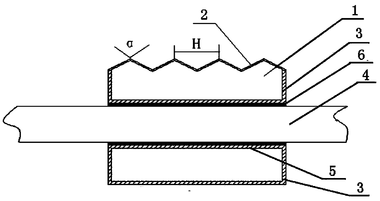
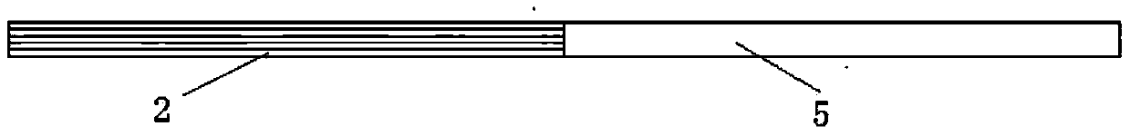
[0026] like figure 1 Shown, a kind of micro concentrating photovoltaic ribbon, it comprises base band 1, and base band 1 has light-receiving surface, back and side, and light-receiving surface is zigzag structure, and light-receiving surface is provided with reflective coating 2, and this reflective coating 2 is made of It is made of a metal or alloy material with a thickness of 500nm~5μm, a reflectivity of more than 65% under the irradiation of light waves in the wavelength range of 300nm~1200nm, and a melting point of more than 232°C. The coating 3 is provided on the back and side, And the coating 3 is made of metal or alloy material with a thickness of 10 μm-25 μm and a melting point lower than 232° C. The back and sides are flat surfaces.

[...


PUM

PropertyMeasurementUnit
Thicknessaaaaaaaaaa
Melting pointaaaaaaaaaa
Thicknessaaaaaaaaaa

Abstract

The invention discloses a micro light-condensing photovoltaic welding ribbon and a preparation process thereof. The micro light-condensing photovoltaic welding strip comprises a base ribbon. The base ribbon is provided with a light receiving surface, a back surface and side surfaces. The light receiving surface is of a saw-toothed structure. A reflecting plating layer is arranged on the light receiving surface. The reflecting plating layer is made of a metal or alloy material with thickness of 500nm-5 [mu]m, a melting point above 232DEG C and reflectivity above 65 percent under the illumination of light waves with wavelength in a range of 300nm-1200nm. Plating layers are arranged on the back surface and the side surfaces and are made of metal or alloy materials with thickness of 10 -25 [mu]m and a melting point below 232DEG C. The micro light-condensing photovoltaic welding ribbon disclosed by the invention has the advantages that not only can the dependence of the welding ribbon on a conductive adhesive bonding technology be reduced and can the manufacturing cost be decreased, but also the micro light-condensing effect can be improved and the power of a module is improved.

Description

technical field [0001] The invention relates to a micro-concentrating photovoltaic welding ribbon and a preparation process thereof, belonging to the technical field of photovoltaic welding ribbons. Background technique [0002] At present, photovoltaic ribbons are the key auxiliary materials for connecting solar cells into strings. Solar cells are connected by ribbons to form a complete electrical path. Light energy is converted into electrical energy through solar cells, and the generated current forms a transmission circuit through ribbons. Use solar energy to provide access foundations. The surface of ordinary ribbon is relatively flat after welding, and the light entering the component is incident on the flat ribbon surface, which cannot be used through mirror reflection; currently there are some special shaped ribbons, and the upper surface of the ribbon is processed into a certain reflective groove Groove structure, the included angle of the reflective groove on the ...

Claims


Application Information

Patent Timeline
IPC IPC(8): H01L31/05H01L31/18
CPCY02E10/50H01L31/0508H01L31/0512H01L31/0547Y02E10/52Y02P70/50
Inventor 张舒杨泽民陈辉
Owner 常州天合光伏焊带材料有限公司
Why Eureka
Try Eureka