High efficiency linear topology structure LED (Light Emitting Diode) driving circuit

A technology of LED drive and linear topology, applied in the direction of lamp circuit layout, electric light source, lighting device, etc., can solve the problem of low power factor, achieve the effect of improving power factor, expanding the input voltage range, and realizing constant current output

Active Publication Date: 2014-04-02
绍兴恒力特微电子有限公司
View PDF3 Cites 4 Cited by
  • Summary
  • Abstract
  • Description
  • Claims
  • Application Information

AI Technical Summary

Problems solved by technology

It has an over-temperature protection function, and some solutions can also pass the surge test, but the power factor is relatively low

Method used


Image

  • High efficiency linear topology structure LED (Light Emitting Diode) driving circuit
  • High efficiency linear topology structure LED (Light Emitting Diode) driving circuit
  • High efficiency linear topology structure LED (Light Emitting Diode) driving circuit

Examples


Embodiment 1

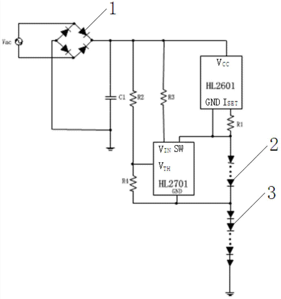
[0023] refer to image 3 , Figure 4 , Figure 5 , a high-efficiency linear topology LED drive circuit, including a rectifier bridge 1, a linear IC regulator HL2601 for controlling constant current output, and a main light string 3, and an input capacitor is connected between the positive output terminal and the negative output terminal of the rectifier bridge 1 C1, the linear IC regulator HL2601 includes a power switch tube SW2, the input terminal of the power switch tube SW2 is V CC terminal, which is connected with the positive output terminal of the rectifier bridge 1, and the output terminal of the power switch tube SW2 is I SET terminal, on which is connected an external resistor R1 for setting the current of the LED, the other end of the external resistor R1 is connected to the GND terminal of the linear IC regulator HL2601, between the linear IC regulator HL2601 and the main light string 3 An intelligent switch regulating circuit with optimized constant current outp...

Embodiment 2

[0029] refer to Figure 7 The difference between this embodiment and the first embodiment is that the intelligent switch regulator circuit is composed of two serially connected intelligent switch regulators, which allows more options for linear LED drive. External resistor divider R3 and R4 control the V of the smart switching regulator HL2701(1) TH terminal voltage, resistor divider R5 and R6 control the V of the smart switching regulator HL2701(2) TH terminal voltage. The GND terminal of the linear IC regulator HL2601 is connected to the SW terminal of the intelligent switching regulator HL2701(1), the GND terminal of the intelligent switching regulator HL2701(1) chip is connected to the SW terminal of the intelligent switching regulator HL2701(2), and the external resistor R1 is used to set the current of the LED. R2 and R7 are the V of the smart switching regulator HL2701(1) and the smart switching regulator HL2701(2) respectively. IN Terminal provides operating curre...

Embodiment 3

[0031] refer to Figure 8 , the difference between this embodiment and Embodiment 1 is that the intelligent switch regulator circuit is composed of three series-connected intelligent switch regulators, this architecture can use a very small input capacitance behind the bridge stack, so as to obtain Higher power factor. External resistor divider R3 and R4 control the V of the smart switching regulator HL2701(1) TH terminal voltage, resistor divider R5 and R6 control the V of the smart switching regulator HL2701(2) TH terminal voltage, resistor divider R9 and R10 control the V of the smart switching regulator HL2701(3) TH terminal voltage. The GND terminal of the linear IC regulator HL2601 is connected to the SW terminal of the intelligent switching regulator HL2701(1), and the external resistor R1 is used to set the current of the LED. R2, R7 and R8 are respectively the V of the smart switching regulator HL2701(1), smart switching regulator HL2701(2) and smart switching reg...


PUM


Abstract

The invention relates to a high efficiency linear topology structure LED (Light Emitting Diode) driving circuit. The high efficiency linear topology structure LED driving circuit comprises a rectifier bridge, a linear IC (Integrated Circuit) regulator for controlling constant output, and a main lamp string, wherein an intelligent switch regulating circuit for optimizing the constant output is connected between the linear IC regulator and the main lamp string; the SW (Southwestern) end of the intelligent switch regulating circuit is connected with the GND (Ground) end of the linear IC regulator; the GND end of the intelligent switch regulating circuit is connected with the main lamp string; the intelligent switch regulating circuit consists of one or more serially connected intelligent switch regulators; each intelligent switch regulator comprises a switch for controlling the opening and closing by threshold voltage; the input end of the switch is the SW end, and the output end of the switch is the GND end; a power resistor or an LED lamp string is connected between the SW end of each intelligent switch regulator and the GND end of each intelligent switch regulator. The high efficiency linear topology structure LED driving circuit has the beneficial effect that the range of input voltage is widened, so that the efficiency and the power factor of the system become higher.

Description

technical field [0001] The invention relates to a high-efficiency linear topology LED driving circuit. Background technique [0002] LED lighting has been widely used in the market, such as commercial lighting, home lighting and so on. At present, more and more lighting appliances are replaced by LED lamps, and many countries are planning to phase out traditional incandescent lamps, and the remaining light sources are mainly energy-saving lamps and LEDs. Although LED lighting has been popularized, there are still many problems in the LED driving circuit. [0003] refer to figure 1 , the traditional AC / DC constant current drive linear topology Example 1 uses a constant current device (CRD) to control the constant current output. It needs some voltage headroom to keep the current constant. It has no over-temperature protection function, and its anti-surge capability is weak. The power factor of this scheme is relatively low. [0004] refer to figure 2 , the traditional...

Claims


Application Information

Patent Timeline
Patent Type & Authority Applications(China)
IPC IPC(8): H05B37/02
CPCY02B20/48Y02B20/40
Inventor 陈龙
Owner 绍兴恒力特微电子有限公司
Why Eureka
Try Eureka