Image diagnostic device and image correction method

一种图像诊断、图像的技术,应用在图像修正技术领域,能够解决图像数据分辨率降低等问题

Inactive Publication Date: 2014-04-02
HITACHI LTD
View PDF8 Cites 8 Cited by
  • Summary
  • Abstract
  • Description
  • Claims
  • Application Information

AI Technical Summary

Problems solved by technology

[0004] The correction technique of Patent Document 1 reduces the resolution of image data to be corrected, and obtains characteristic information through a Laplacian filter.

Method used


Image

  • Image diagnostic device and image correction method
  • Image diagnostic device and image correction method
  • Image diagnostic device and image correction method

Examples


Embodiment 1

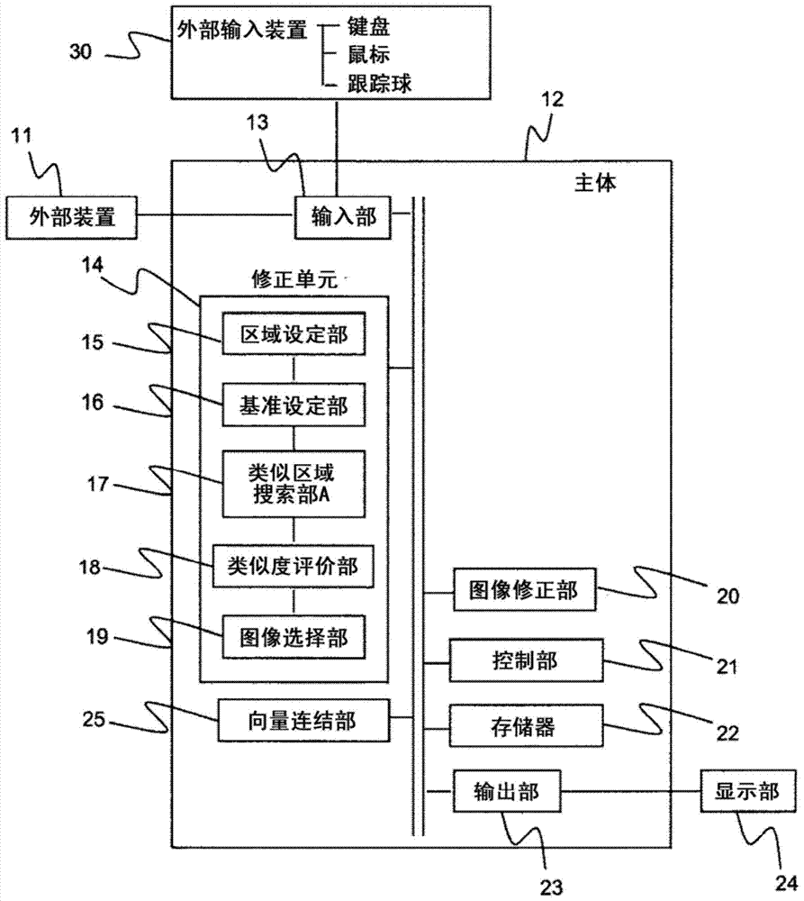
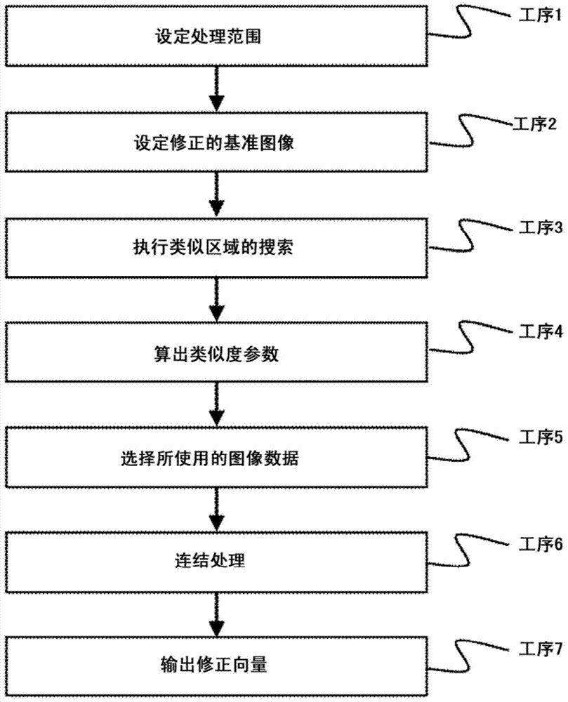
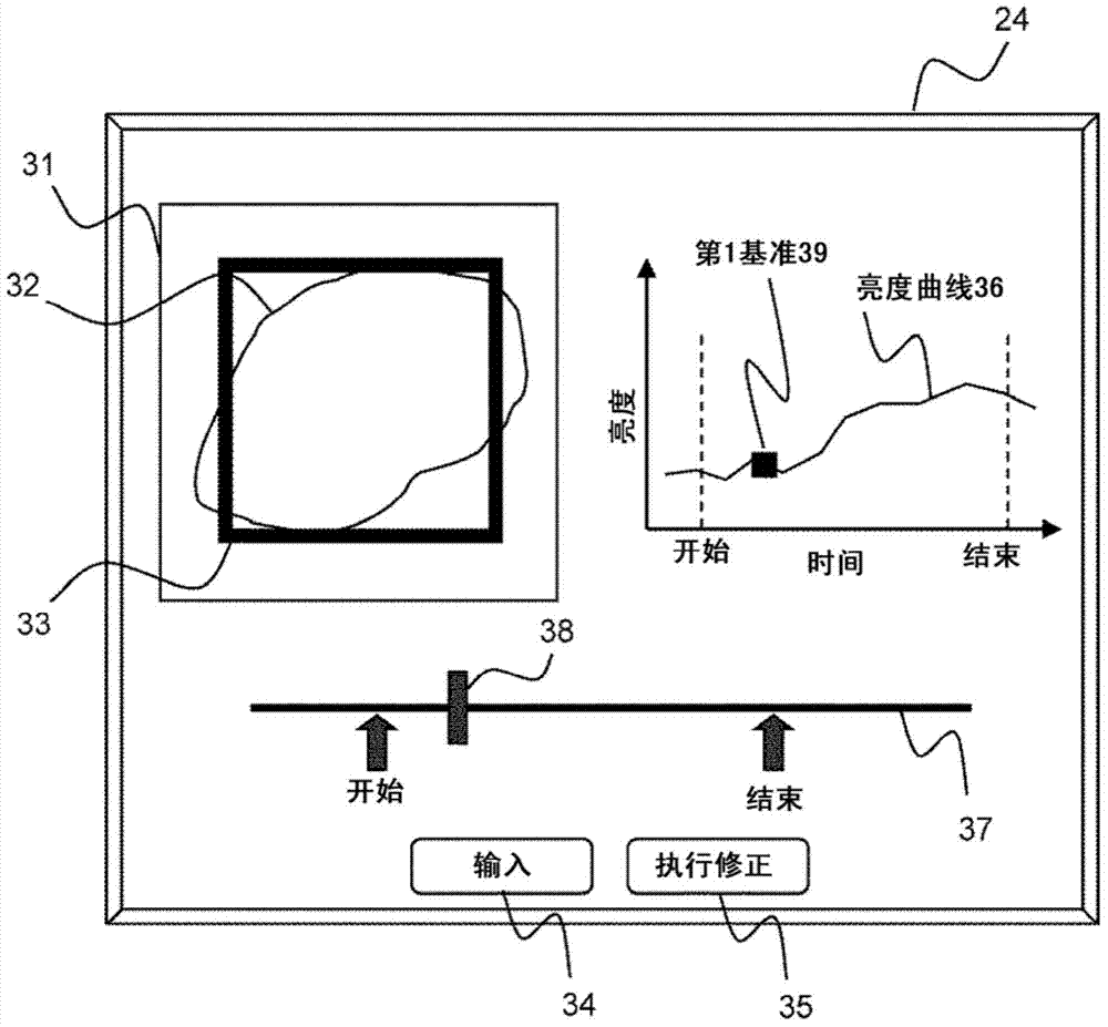
[0038] Below, use Figure 1 to Figure 11 , an example of the configuration of the image diagnostic apparatus as the first embodiment will be described. The first embodiment relates to an image diagnostic apparatus capable of correcting positional displacement of an imaging target with respect to time-series image data from an external device and improving reliability of correction results. That is, the first embodiment is an embodiment of an image diagnostic apparatus that corrects time-series image data, and the image diagnostic apparatus includes: a correction unit 14 that corrects time-series image data based on the degree of similarity with a reference image. Select image data to be corrected, and output a correction vector representing a positional shift of the selected image data; an image correction unit 20 that performs correction processing on the image data based on the correction vector to create corrected image data; and a display unit 24 , which displays an image...

Embodiment 2

[0081] The image diagnostic apparatus of Embodiment 2 further includes a distortion correcting unit 26 in addition to the image diagnostic apparatus of Embodiment 1, and is an image diagnostic apparatus capable of responding to a deformation movement of an imaging object. That is, the image diagnostic apparatus of Embodiment 2 relates to an image diagnostic apparatus having a configuration including a deformation correction unit 26 in addition to the above-mentioned image diagnostic apparatus of Embodiment 1, and the deformation correction unit 26 includes: a region dividing unit 27 , which divides the region to be corrected set by the correction unit 14 to set a plurality of divided regions; the second similar region search unit 28 searches for a region similar to the reference image for a plurality of divided regions, and calculates the corrected region. vector; and an error correction unit 29 that performs error correction on the correction vector calculated by the second si...


PUM


Abstract

Provided is an image diagnostic device with which it is possible to correct location misalignment of an image capture subject, and to improve the reliability of the result of the correction, in time series image data. An image diagnostic device is configured of: an input part (13) which receives image data input; a correction unit (14) which computes a correction vector which denotes location misalignment of an image capture subject, and selects image data used with an image correction unit; an image correction part (20) which carries out a correction process on the image data based on the correction vector and creates corrected image data; a control part (21) which controls the correction unit and the image correction part; a memory (22) which stores the corrected image data and measurement data as stored data; an output unit (23) which outputs the stored data externally; a display unit (24) which displays the stored data; and an external input device (30) where an operator makes an input operation.

Description

technical field [0001] The present invention relates to image processing for correcting the positional deviation of an imaging object with respect to time-series image data, and in particular to an image correction technique for evaluating the reliability of correction results and implementing correction processing. Background technique [0002] Time-series image processing techniques for extracting temporal changes of an imaging target by performing image processing such as addition or subtraction on a plurality of image data acquired at different times are widely used in various fields. In particular, in the field of medical image diagnosis, along with the high performance of devices, technical development of functional evaluation technology for evaluating the properties of tissues is also in progress, in addition to the technology for imaging the shape of tissues that has been the mainstream in the past. Having attention. Ultrasonic diagnostic images take less time to ca...

Claims


Application Information

Patent Timeline
Patent Type & Authority Applications(China)
IPC IPC(8): A61B8/00A61B5/055A61B6/03G06T1/00
CPCA61B6/5211A61B6/469A61B2576/00A61B6/5264A61B6/486G06T7/0012A61B8/5246A61B8/485A61B8/4245G06T2207/30004G06T7/0024A61B6/5241A61B5/055A61B8/5215A61B6/58A61B6/481A61B6/5235A61B6/032A61B6/461G06T7/003A61B8/5207G06T2200/24G06T2207/20104G06T7/337G16H30/40
Inventor 吉川秀树东隆
Owner HITACHI LTD
Why Eureka
Try Eureka