Atomizing device for deaerators

A technology of atomization device and deaerator, which is applied in the direction of spraying device, spraying device, spraying device with movable outlet, etc., which can solve the problem of non-condensable water rotary atomization, unsatisfactory atomization effect, and ineffective reduction of deaerator Evaporated water and other issues, to achieve good atomization effect, reduce the effect of evaporated water

Inactive Publication Date: 2014-04-09
CHONGQING JUKANG BUILDING MATERIAL
View PDF0 Cites 1 Cited by
  • Summary
  • Abstract
  • Description
  • Claims
  • Application Information

AI Technical Summary

Problems solved by technology

The current atomization device of the rotary film thermal deaerator cannot rotate and atomize the passing condensed water or supplementary

Method used


Image

  • Atomizing device for deaerators

Examples


Embodiment Construction

[0011] Below in conjunction with accompanying drawing and embodiment the technical solution of the present invention is further described:

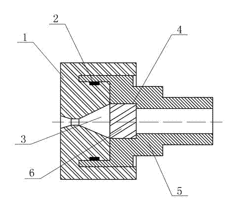
[0012] like figure 1 As shown, the present invention provides an atomizing device for a deaerator, which includes a housing 1 and a cylindrical connecting sleeve 5 cooperating with the housing 1. The connecting sleeve 5 is provided with an inner through hole, and the housing 1 is provided with a spray hole. 3. A cylindrical valve body 4 is installed in the inner through hole of the connecting sleeve 5. There are 8 axially concave thread grooves 6 on the outer surface of the cylindrical valve body 4. The helical angle of the thread groove 6 is 15° °, the nozzle hole 3 is formed by connecting the left and right conical nozzle holes through connecting holes. As a whole, it is arranged in the housing 1, and the housing 1 with internal threads is screwed with the left end of the connecting sleeve 5 with external threads, so that the cylindric...


PUM


Abstract

The invention relates to an atomizing device, in particular to an atomizing device for deaerators. The atomizing device comprises a housing and a cylindrical connecting sleeve matching with the housing. The connecting sleeve is provided with an inner through hole. A spout is arranged in the housing. A cylindrical valve is mounted in the inner through hole of the connecting sleeve. The outer surface of the cylindrical valve is provided with 6-8 axial concave spiral grooves. Passing water is rotated and atomized by the atomizing device according to the technical scheme, and atomizing effect is good.

Description

technical field [0001] The invention relates to an atomizing device, in particular to an atomizing device for a deaerator. Background technique [0002] In the boiler feed water treatment process, oxygen removal is a very critical link. The deaerator is an important auxiliary equipment in the heat recovery system of the steam turbine generator set, and the atomization device is an important part of the deaerator, which is used to atomize the condensed water or supplementary water, and the atomization device directly affects the deaerator The atomization device of the deaerator should have a suitable structure, and the atomization effect of the atomization device should be good under the appropriate flow rate and pressure difference. The current atomization device of the rotary film thermal deaerator cannot rotate and atomize the passing condensed water or supplementary water well, so that the amount of evaporated water in the deaerator cannot be effectively reduced, and the...

Claims


Application Information

Patent Timeline
IPC IPC(8): B05B1/02C02F1/20
CPCB05B1/06B05B3/08C02F1/20
Inventor 周炫张信聪
Owner CHONGQING JUKANG BUILDING MATERIAL
Why Eureka
Try Eureka